The Event function of DataMesh One provides users with rich AR experience and collaboration functions, allowing users to create and participate in immersive AR events.
Here is a description of the Event function of DataMesh One:
New Event: With DataMesh One, users can create new virtual reality events. When creating a new event, users can set basic information such as the name and valid date of the event and set the scenario for the AR scene. The scenario defines the scenes, roles, actions, and interaction processes in the event.
Event management: As the creator and owner of the event, users can manage the event. This includes editing event information, modifying scenario settings, and more. The event management function enables users to flexibly control and customize the event.
Play event scenarios: The event creator can guide the event by playing the scenario of the event. During the event, the event creator can gradually play the scenes and guide participants to complete various tasks and experiences according to the scenario.
Participate in events: DataMesh One allows users to participate in virtual reality events created by others. Users can select events of interest from the event list and enter the event scene through devices such as HoloLens, mobile phones, and tablets. Event participants can watch the scenario, but do not have permission to play the scenario. This provides convenience for observing, learning, and sharing events.
New event
Steps
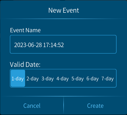
1. Click the add button in the event list to go to the New Event interface.
2. In the New Event interface, fill in the Event Name (default format yyyy-mm-dd hh:mm:ss) and select the event’s Valid Date.
3. Click the Create button to open the event setting interface.
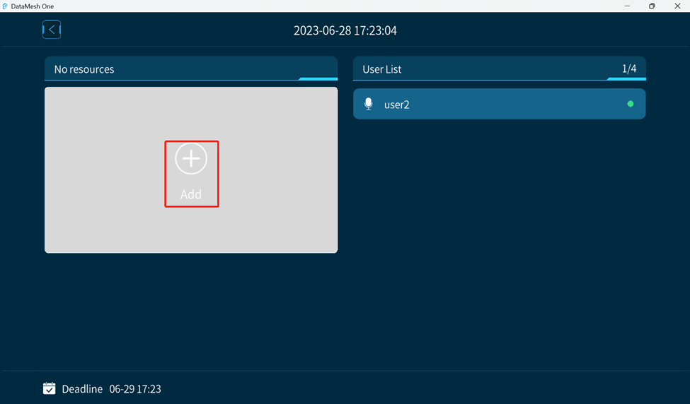
4. In the event setting interface, click Add button.
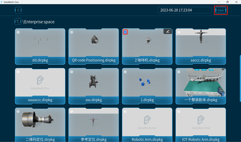
5. Open the folder where the scenario is located, select the scenario, and click Save to add the scenario to the event.
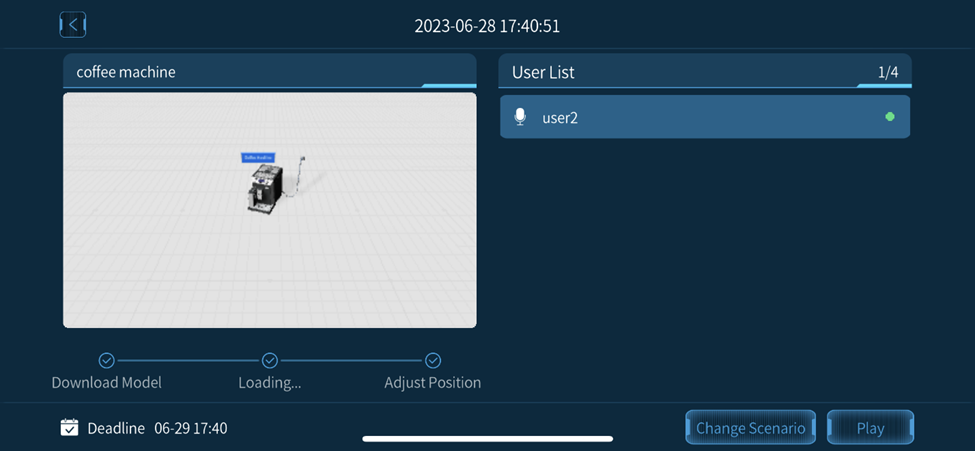
6. Click on a blank space in the scene to place a model.
7. Wait for the scenario to finish loading to complete the creation of the event.
Edit event
To modify an already created event, such as changing the event scenario or modifying the event name, please follow these steps:
Note: Only the owner of the event has permission to edit the event.
1. Click on the event to be edited in the event list to enter the event details page.
2. On the event details page, click the Change Scenario button.
3. To replace an existing scenario with a new one, simply click on the Change Scenario button.
4. After editing is complete, click the “<” button in the upper left corner to exit the event details page and return to the event list page.
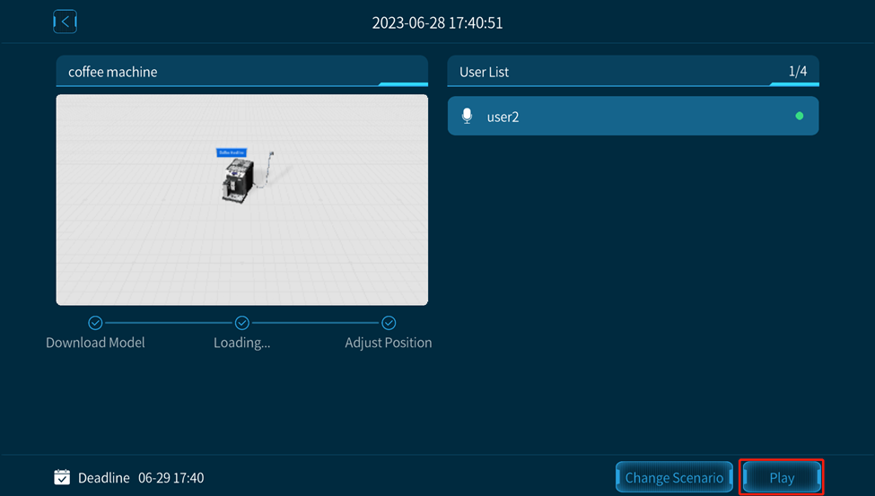
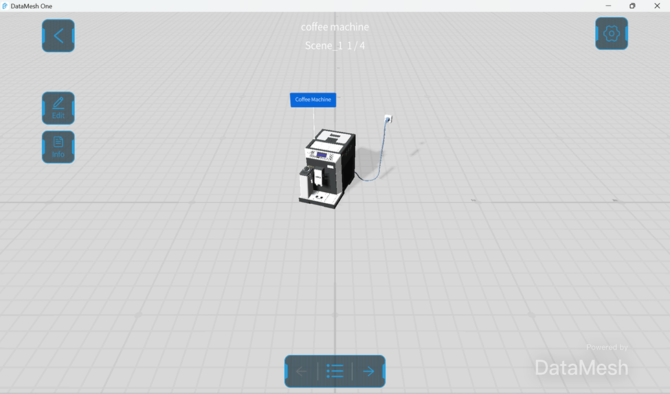
Play event
To play a created scenario in the event details page, follow these steps:
1. Select the event to be played in the event list and enter the event details page.
2. Wait for the models in the event to download and load.
3. After all participants are ready, the creator of the event can click the Play button to start playing the scenario.
4. Place the models and adjust their position and orientation to ensure that the scenario can be played in the correct scene. For more information on placing models and adjusting their position, please refer to Position mode.
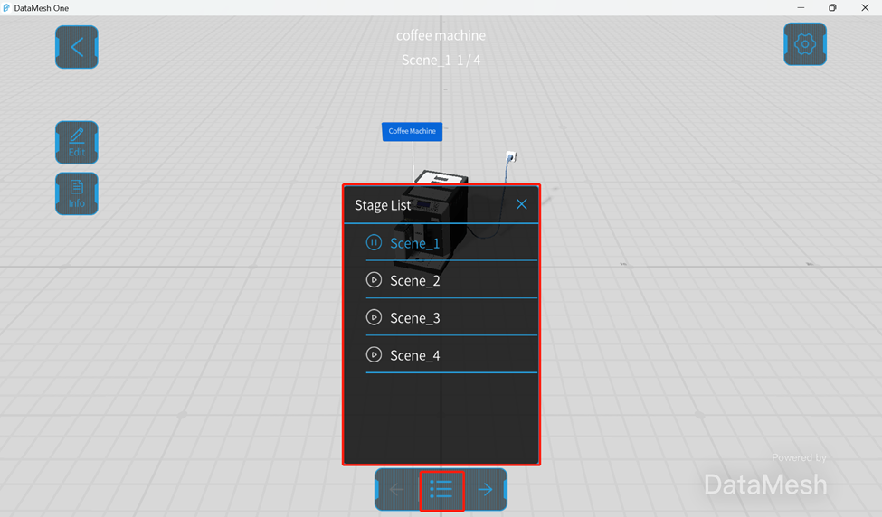
5. Click the Stage List button to open the scenario’s Stage List. Click the scene name in the list to play the scene on a single page.
6. After the scenario is finished playing, click the “<” button in the upper left corner to exit the event.
To facilitate playback and viewing experience, the edit mode can be used to adjust the position, size, rotation angle, and transparency of models, sub-objects, tools, and other resource content in the scenario.
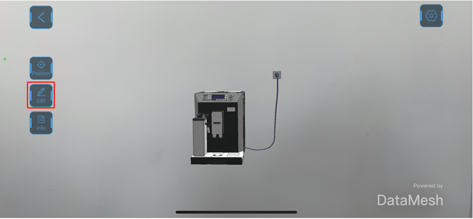
Edit mode settings
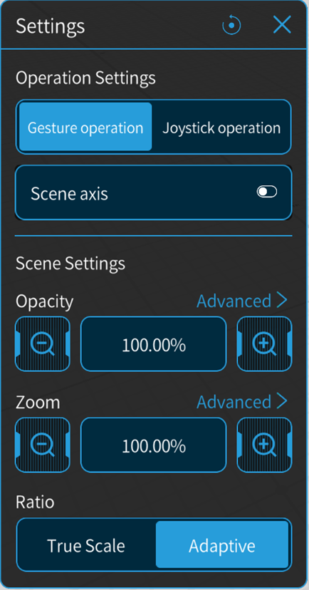
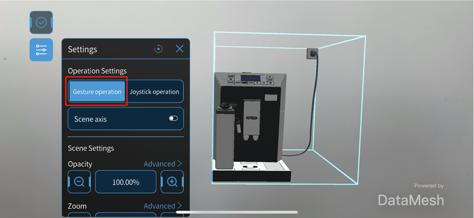
After opening the resource, you can enter Edit mode by clicking on the Edit button . Then click the adjust function button to open the Settings pane of edit mode.
Operation Settings: There are two types of operation modes in edit mode, Gesture operation and Joystick operation. You can switch between the two modes here.
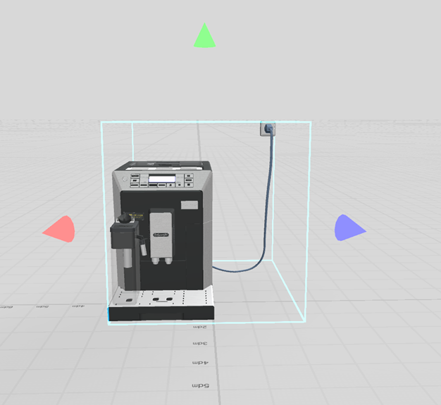
Scene axis: You can enable the Scene axis for Gesture operation, which can quickly and accurately move objects along a straight line. After enabling the Scene axis, cone-shaped arrows corresponding to the X, Y, and Z axes appear around the model. Click and drag the Scene axis to move the model along that axis.
Scene Settings: In the Settings pane of edit mode, you can adjust the Opacity and Zoom of the resource, and further adjust the editing precision through Advanced options.
Gesture operation
When using gesture operation, you can adjust the position, size, and rotation angle of the model or sub-object by using gestures such as moving, scaling, and rotating. This method is more flexible and intuitive and can quickly complete editing operations. It is suitable for editing scenes, models, and other content on touch screens, such as on mobile devices.
Here are the detailed steps for using gesture operation on a mobile device:
1. After opening resource, click on the Edit button to enter the edit mode.
2. After entering the edit mode, click the adjust function button to enter edit mode Settings, and then select Gesture operation.
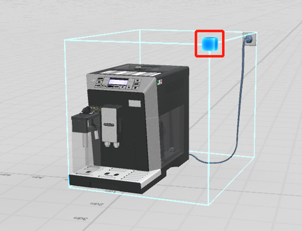
3. Click the object to be edited, and a blue highlight border will appear around the object. Use Gesture operation to move, scale, and rotate the object.
a. Move the object: Click and drag anywhere inside the border to move the object.
b. Scale the object: Click on one corner of the blue border around the object to create a blue square. Drag the square to scale the object.
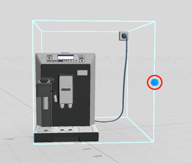
4. Rotate the object: Hold down the center of one of the blue borders to create a blue sphere. Drag the sphere to rotate the object.
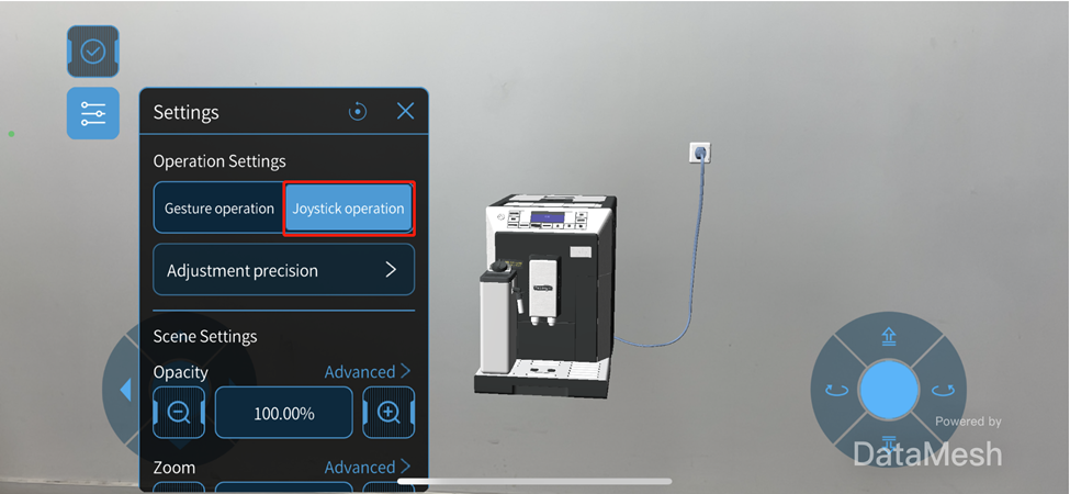
Joystick operation
You can also use the joystick to edit the model or sub-object.
The specific steps for using joystick operation are as follows:
1. After opening the resource, click on the Edit button to enter the edit mode.
2. After entering the edit mode, select Joystick operation in the edit mode Settings. You can also adjust the sensitivity, rotation angle, and other parameters of the joystick by adjusting the precision.
3. Click to select the object to be edited, and a blue highlight border will appear around the object.
4. Use the joystick to move and horizontally rotate the object.
DataMesh One offers various methods for positioning resources in MR mode. These positioning methods allow users to adjust the position, distance, height, and angle of resources to ensure accurate placement.
Adjust function
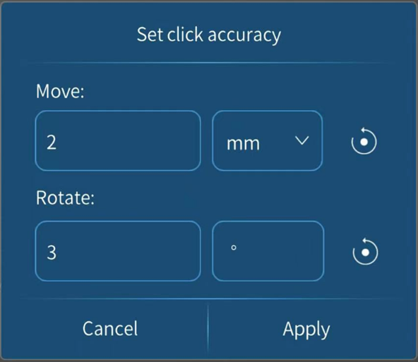
In DataMesh One’s position mode, users can fine-tune the precision of adjustments. It includes the following options:
Movement: Adjusts the unit size of each movement. The default unit is millimeters (mm), but users can select other units such as centimeters (cm), decimeters (dm), or meters (m) as needed. By adjusting the unit size, users can achieve precise position adjustments.
Rotation: Users can adjust the angle of each rotation. The default angle is 3 degrees (3˚), but users have the flexibility to customize the rotation angle for more precise adjustments.
The steps for adjusting accuracy are as follows:
The steps for adjusting the click accuracy are as follows:
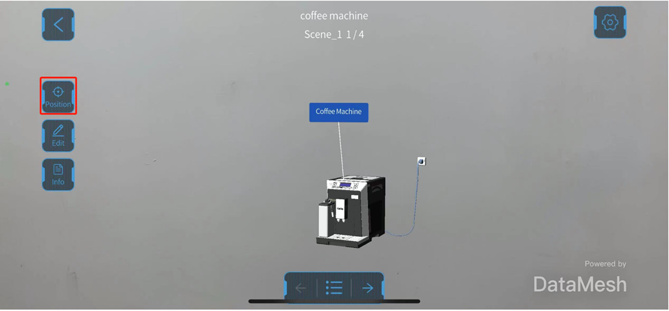
1. After opening the resource, you can click on the Position button to enter position mode.
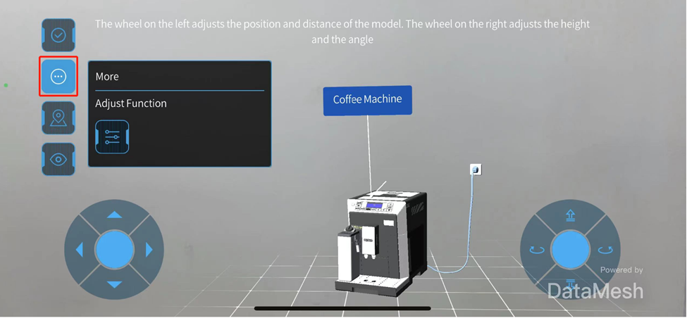
2. After entering position mode, click on to open the More function pane.
3. To open Set click accuracy window, click on the adjust function button .
4. According to specific needs, personalize the click accuracy settings, and click Apply to complete the settings.
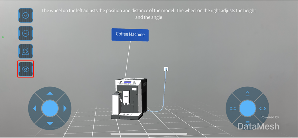
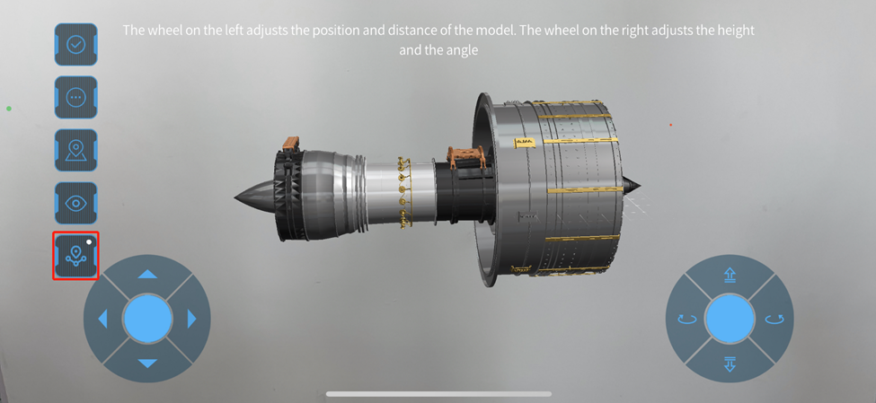
Wheel adjustment
Wheel adjustment method can more accurately adjust the position, distance, height, and angle of resources.
Steps
1. After opening the resource, you can click on the Position button to enter position mode.
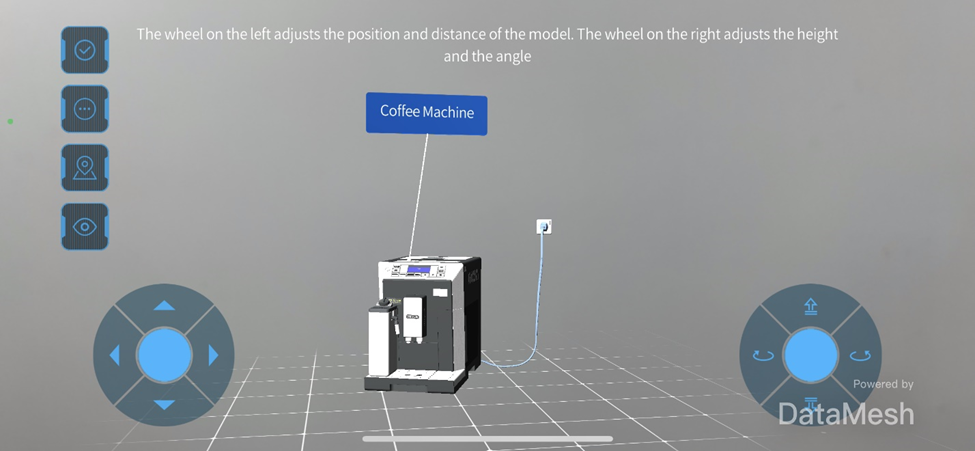
2. After entering position mode, the wheel adjustment method is displayed by default.
3. Use the wheels to adjust the position, distance, height, and angle of the resource.
When using the wheel adjustment method, in addition to using the left wheel to control the resource’s forward, backward, left, and right movement on the horizontal plane, use the right wheel to control the resource’s height and orientation angle.
4. Click on to complete positioning.
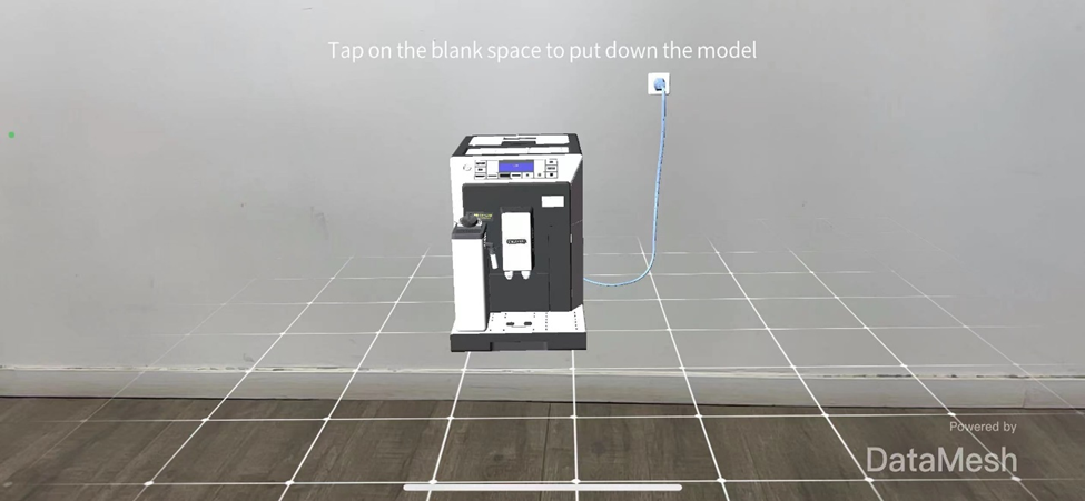
Gaze mode
In Gaze mode, resources are placed based on where the user is looking. Users only need to look at or move the camera view to the desired location, click on the blank space on the screen, and the resource will be placed in that location. The advantage of placing resources in Gaze mode is that models can be quickly placed on recognized surfaces in the surroundings.
When opening a resource, you will enter Gaze mode by default. After placing the resource, if you need to use Gaze mode to place the resource again, you can follow these steps:
1. Click on the Position button to enter the position mode.
2. Click on the gaze mode button to enter Gaze mode.
3. After entering the Gaze mode, move the camera (view) and click on the blank space on the screen to place the resource.
4. Click on the button to complete positioning.
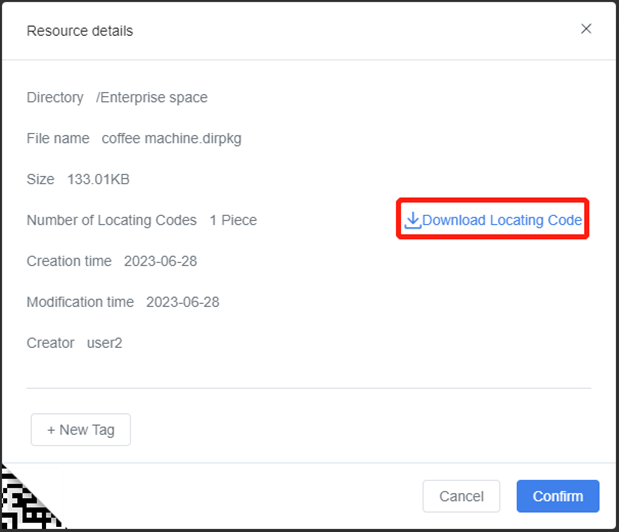
QR Code positioning
By scanning the QR code you can more accurately position virtual objects, ensuring that they correspond to real-world physical objects and improving the user’s experience and learning effectiveness. For example, in an exhibition, you may need to precisely place a virtual exhibit in the same location as a real exhibit, which enables visitors to observe the virtual exhibit’s effect in the real environment.
The steps for scanning the code to position resources are as follows:
1. On FactVerse Services, go to the Resource page in the Digital Twin module, find the scenario file you need.
2. Open the Resource details window and download locating code.
3. Open scenario in the resources list on DataMesh One.
4. Click on the Position button to enter the position mode.
5. Click button to scan QR code.
6. Scan the QR code downloaded in step 2.
7. Click on to complete positioning.
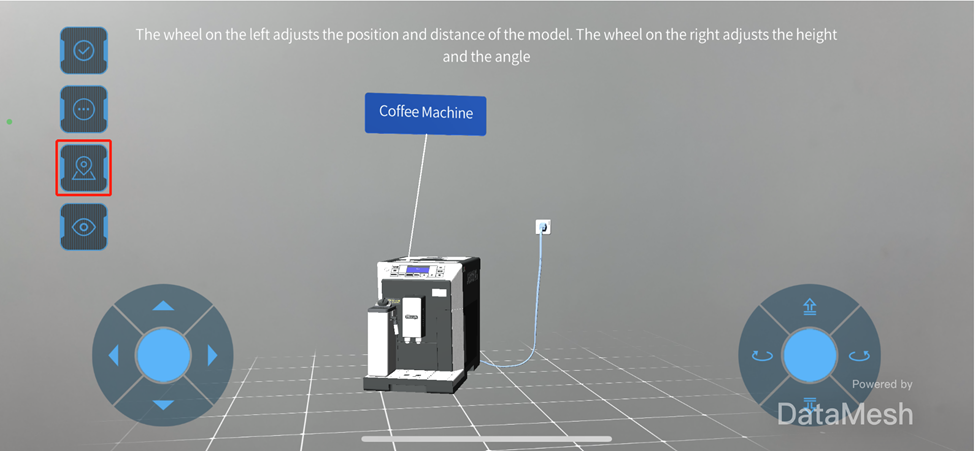
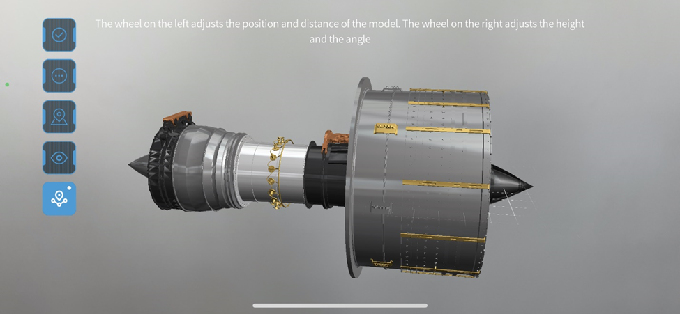
Spatial anchor positioning
A spatial anchor is a positioning anchor relative to physical space. It uses the device’s camera to scan the surrounding environment to determine the device’s location, then determines the position of resources relative to that location through location algorithms.
Note:
The spatial anchor positioning function is only visible to all users under the corporate tenant when the corporate administrator has configured the correct Account ID, Account Key, Account Domain in the Spatial Location Configuration in Enterprise Management > Enterprise Settings on FactVerse Services.
The spatial anchor positioning function is only applicable to scenarios.
It is recommended to add anchors in flat, important, and easily readable locations.
In the current version, the spatial anchor positioning mode is turned off by default and you need to be manually entered into the location mode to turn it on; except for the scenario creator, other users cannot create, update, and delete anchor data on the scenario.
The HoloLens end uses the same process as mobile devices.
Icon meaning:
: The spatial anchor positioning mode is not turned on, and clicking the icon can switch the spatial anchor positioning mode to the on state.
: The spatial anchor positioning mode has been turned on, but no created spatial anchors have been found around, and clicking the icon can switch the spatial anchor positioning mode to the off state.
: Spatial anchor positioning has been turned on, and spatial anchors have been recognized around and used for positioning. Clicking the icon can switch the spatial anchor positioning mode to the off state, and long pressing the icon can delete all created anchors in this scenario.
Permissions
Scenario creator: Create, update, use, delete.
Other viewers: Use permission.
Spatial positioning configuration
Users with enterprise management permissions can perform the following spatial positioning configuration:
The Spatial Anchors function requires the use of the Azure Spatial Anchors Service. For more information on the service charge, please refer to Spatial Anchors pricing.
2. Log in to FactVerse Services.
3. Enter the Enterprise Settings page in the Enterprise Management module.
4. In the Spatial Anchor Configuration, enter the Account ID, Account key, and Account domain of the spatial anchors account created in step 1.
5. Click the save button to save the spatial positioning configuration.
With the above configuration, all members of the enterprise can use the spatial anchor positioning function.
Add spatial anchors to scenarios
The scenario creator can add spatial anchors to the scenario, the specific steps are as follows:
1. Open the scenario, complete the initial position placement, and click to turn on the spatial anchor positioning mode.
2. After the spatial anchor icon changes to the turned-on state , the icon in the upper right corner of the icon is gray, which means that there are no spatial anchors around you. You can create spatial anchors around you through the wheel, scanning, and gaze mode.
Wheel mode
1. After turning on the spatial anchor positioning mode, you can use the wheels to adjust the position of the model.
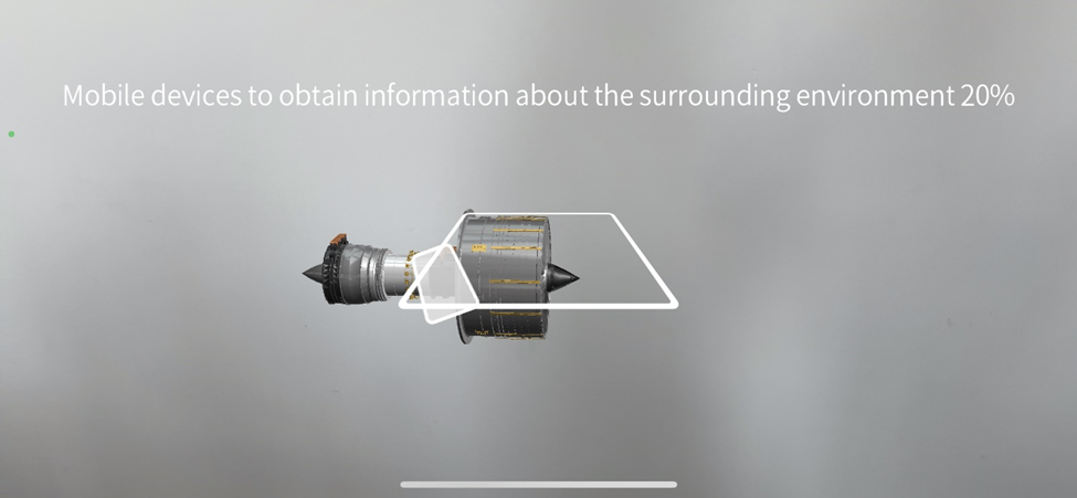
2. Click , at this time it will prompt you to move your phone to recognize the surrounding environmental information.
3. After the information is collected, a spatial anchor is created. At this time, the dot in the upper right corner of the spatial anchor turns green , indicating that you are using the surrounding spatial anchor for positioning
4. If you need to create multiple spatial anchors in succession, you can move your phone. When the dot in the upper right corner of the anchor icon turns gray (indicating that no spatial anchors are recognized around you), use the wheel, gaze, or scan mode to create a new spatial anchor. Note: If you adjust the current positioning when the dot in the upper right corner of the anchor icon is green, it will update the positioning information of the current anchor and will not create a new anchor.
QR Code positioning mode
1. After turning on the spatial anchor positioning, use the scan mode to place the model at the position of the QR code positioning.
2. Click , at this time it will prompt you to move your phone to recognize the surrounding environmental information. After the recognition is over, the dot turns green, and a spatial anchor is created.
3. If you need to create anchors in succession, just move your phone. When the dot in the upper right corner of the anchor icon turns gray, scan the QR code again or use other modes to position, and a new spatial anchor will be created.
Gaze mode
The process of creating anchors in gaze mode is like scan mode, but because the characteristic of gaze mode is to allow users to place models faster, rather than precise positioning, the created spatial anchors’ position may not be accurate. It is recommended to use scan mode to create accurate spatial anchors and use the wheel to fine-tune and correct anchor positioning.
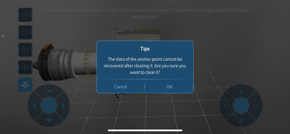
Clear spatial anchors
The scenario creator can clear all the created spatial anchors in the scenario.
The specific steps are as follows:
1. After opening the scenario, in the position mode, turn on the spatial anchor positioning mode.
2. Long press the spatial anchor positioning icon to pop up the confirmation window.
Note: The anchor data cannot be recovered after being cleared.
3. Click OK in the prompt window to confirm the removal of all spatial anchors in the scenario.
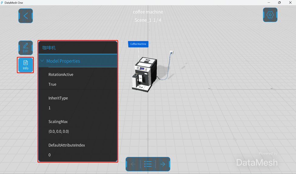
In DataMesh One, an information pane is provided to help users view resource information and better understand the content in the scene. Through the information pane, users can obtain the following resource-related information:
Resource name: Displays the name of the resource, helping users quickly identify the selected resource.
Model properties: Provides related information such as model attributes and node attributes. These properties information can help users understand the characteristics and structure of the model.
Steps
1. In the case of opening a resource or playing an event, click on the resource to be viewed in the scene.
2. Click on the Info button on the right side to expand the resource information pane.
3. In the resource information pane, you can view more resource information, such as model name and node name.
4. To collapse the resource information pane, click the information button again.
In DataMesh One, you can view 3D models, 2D resources, scenarios, and other content by opening resources.
Before opening resources, please make sure your device is connected to a stable network for fast downloading and loading of resources. In addition, it should be noted that larger 3D models may take longer time to load.
In MR viewing mode, resources can be placed anywhere in the real world. For example, you can place a virtual model on a table or on the floor. If you need to adjust the position of a resource that has already been placed, you can enter position mode to reset the position. For more information, please refer to Position mode.
In 3D viewing mode, resources will automatically appear in front of your view. You can rotate, zoom, and move the resources using gestures or joysticks to better observe and experience. If you need to edit the position, rotation angle, scale, or transparency of a resource, you can enter Edit mode to perform the operation. For more information, please refer to Edit mode.
3D models
Please follow the following steps to open 3D models from resources list:
1. In the Resources interface, click on the folder containing the 3D models to open the resources list under that folder.
2. You can perform a fuzzy search of resources by entering keywords in the search box.
3. Click on the 3D model file you want to view in the resources list.
4. Start downloading and loading resources.
In MR viewing mode, the model center is placed at (0, 0, 0) and you will enter position mode. Move your mobile device and click on the blank space in the screen to place the model.
In 3D viewing mode, the model will automatically appear in front of your view after it is loaded.
5. If you need to adjust the position of a model that has already been placed, you can enter position mode to reset the position. For more information, please refer to Position mode.
6. If you need to adjust the position, rotation angle, scale, or transparency of the model, you can enter Edit mode for editing. For more information, please refer to Edit mode.
2D resources
DataMesh One also supports opening 2D resources such as images, videos, and PDF files. The opening process is the same as for 3D models, and they will appear in front of the screen for convenient viewing and operation by the user.
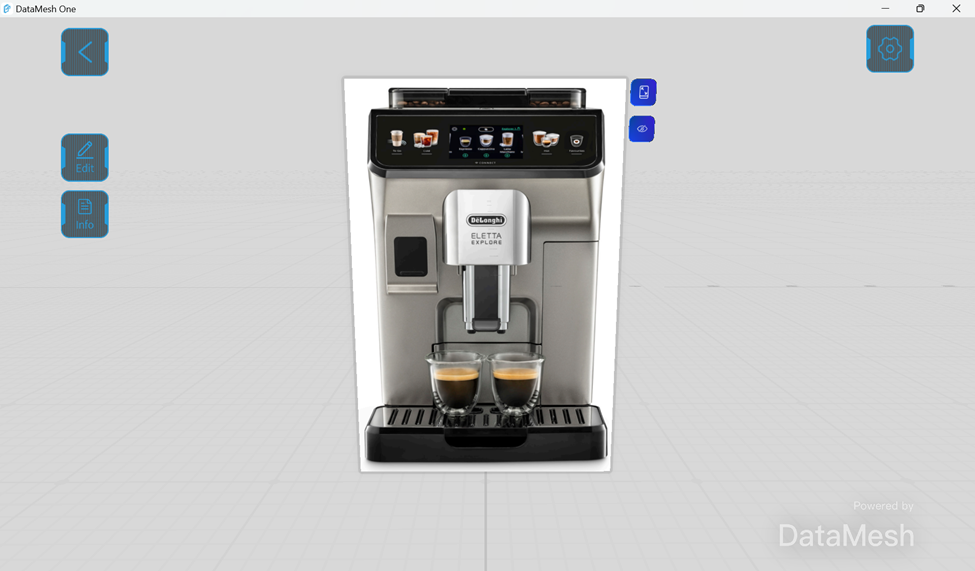
Image
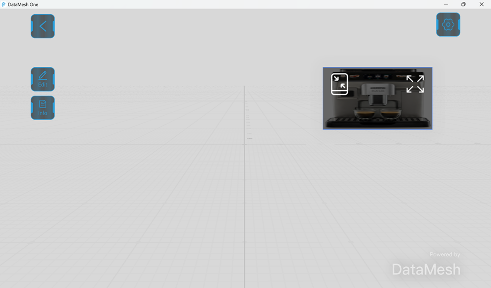
After opening an image, you can minimize, hide, and view the image in full screen.
: Minimize. Clicking on this option will minimize the resource and fix it in the upper right corner of the screen for convenient viewing at any time.
: Hide. Clicking on the Hide icon will hide the image. After hiding the image, a Show icon will appear. Clicking on the Show icon, the image will be displayed again.
: View in full screen.
: Unminimize. Select the image in the minimized state in the upper right corner of the screen, and then click to unminimize the image.
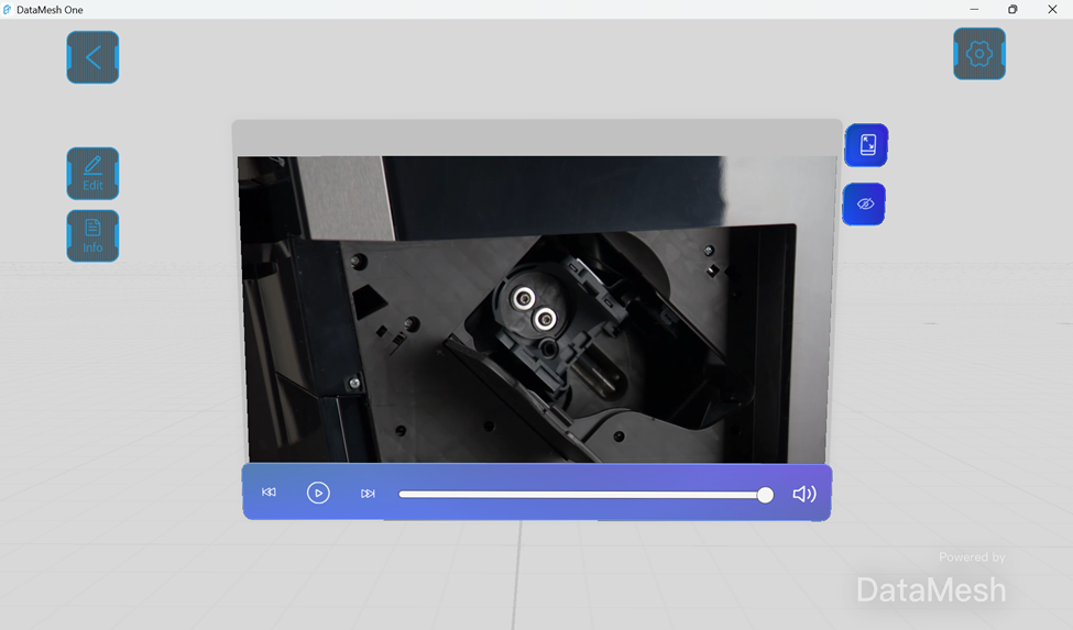
Video
After selecting a video, you can use the control buttons to play, pause, fast forward, rewind, adjust the progress bar, and control the volume.
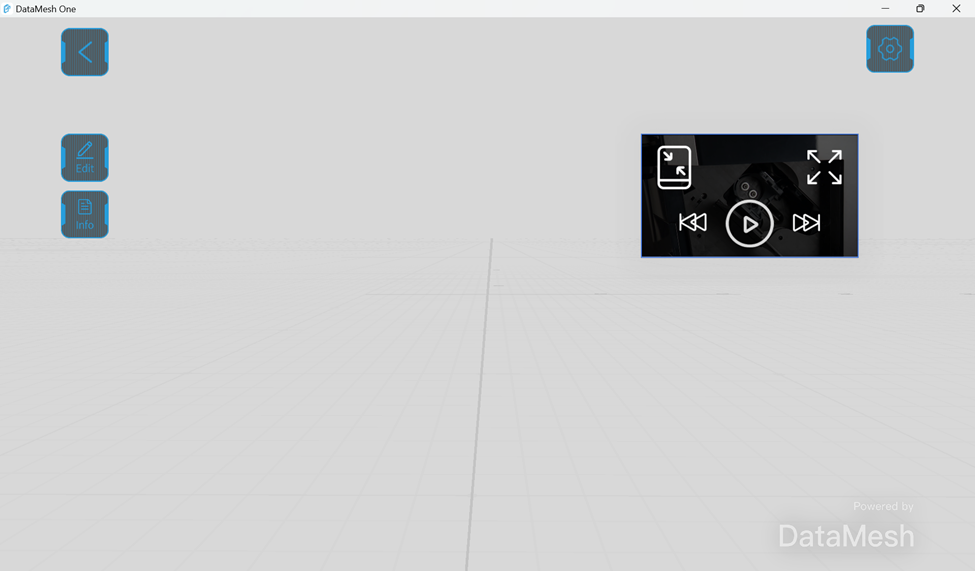
After clicking on the minimize icon, the video will minimize and be fixed to the upper right corner of the screen. You can click on the minimized video and use the control buttons to play, pause, fast forward, rewind, and adjust the video progress. You can also unminimize the video or watch the video in full screen.
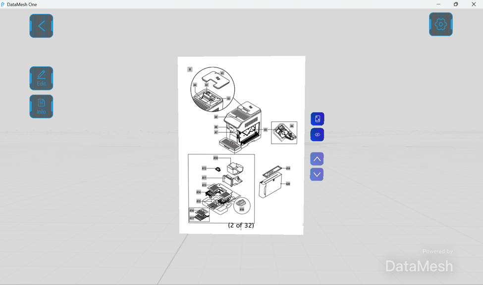
PDF file
DataMesh One supports operations such as page turning, minimizing, and hiding PDF files.
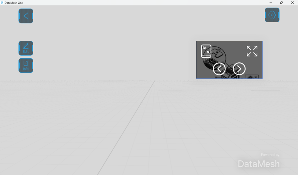
Clicking will minimize the PDF file and fix it to the upper right corner of the screen. You can click on the minimized PDF file and choose to turn pages, deselect minimize, or read in full screen mode.
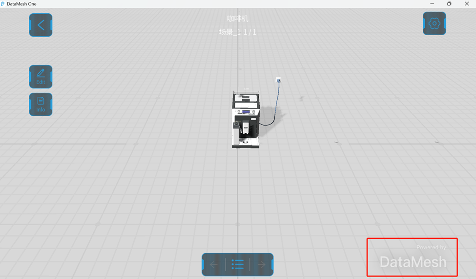
Scenario
Scenario playback is an important function in DataMesh One. Before opening a scenario, you need to select the scenario folder in the Resources interface. Then, you can click on the scenario file you want to play and open it in the scene.
Steps
1. Click on the folder where the scenario is in the Resources interface.
2. Click on the scenario you want to play and open it in the scene.
3. After opening the scenario, you can set the position and edit the models and other resources in it. For more information, please refer to Position mode and Edit mode.
4. Click on the Stage List button to open the Stage List of the scenario. Clicking on the name of a scene in the list will play that scene on a separate page.
Scan the code to open models and scenarios
DataMesh One also supports opening models and scenarios through scanning the code. If you need to open models and scenarios through scanning the code, please follow these steps:
1. On FactVerse Services, go to the Resource page in the Digital Twin module, find the model or scenario file you want to view, and open the Resource details window.
2. Click on the bottom left corner of the Resource details window, and the window will display the link and QR code information of the resource.
3. In the main interface of DataMesh One, click on the scan button , scan the QR code of the resource in step 2, load and open the model or scenario.
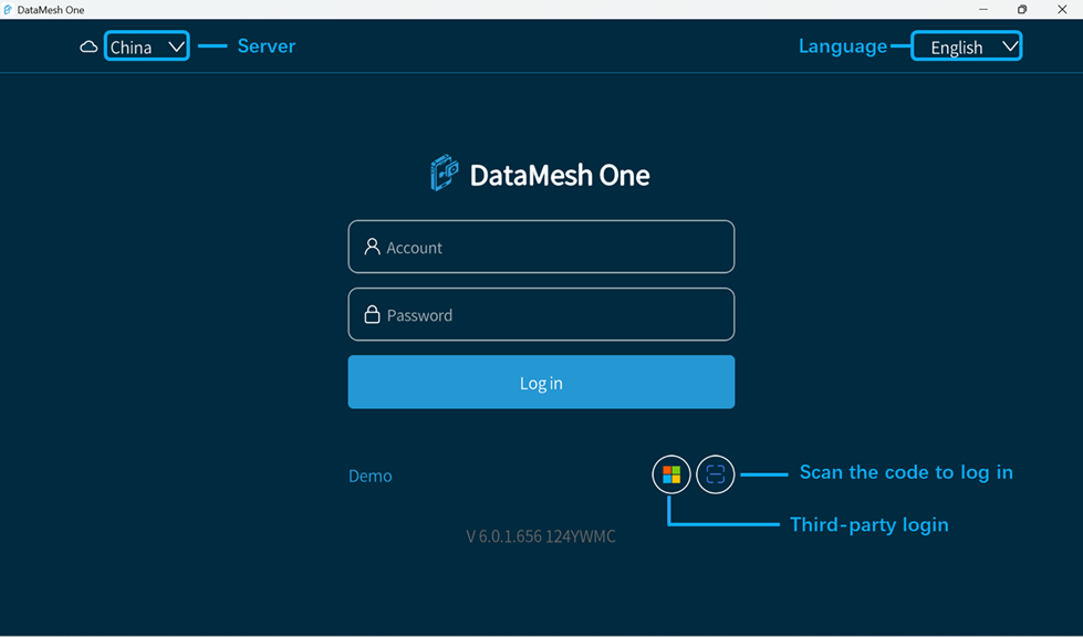
Language: You can switch the interface language to Simplified Chinese, English, Japanese, and Traditional Chinese.
Server: The server that the enterprise account belongs to.
: Private deployment icon. When logging in with a private deployment server for an enterprise account, you need to set a private deployment exclusive service code. Users can click on this icon to set the private deployment exclusive service code.
Demo: It allows users to watch built-in models, scenarios, and events provided by DataMesh as a guest.
Third-party login: For more details, please refer to Third-party login.
Regular login
On the login interface of DataMesh One, use your account and password to log in.
Steps
1. Open the Login interface of DataMesh One.
2. Select the Language and Server that the enterprise belongs to.
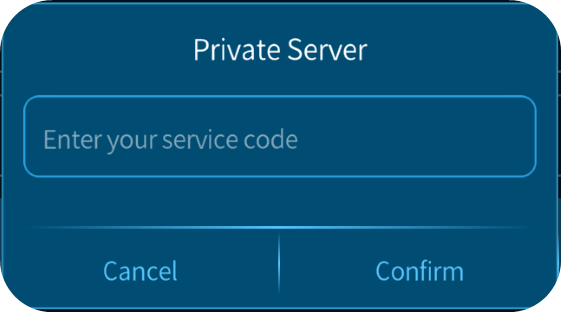
3. If your enterprise has deployed a private server, you must set an exclusive service code before logging in. The specific steps to set it up are as follows:
a. Click Private deployment icon .
b. In the Private Server dialog box, enter the enterprise’s private deployment exclusive service code.
c. Click Confirm to return to the login page. The server’s name on the login page will be displayed as the exclusive service code you have set.
4. Enter your Account and Password.
5. Click the Log in button.
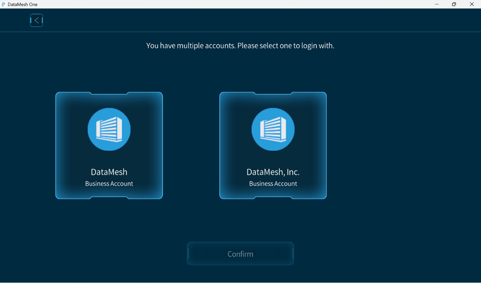
a. If you belong to only one enterprise account, you will directly enter the main interface after successfully logging in.
b. If you have multiple enterprise accounts, a list of enterprise accounts will be displayed for you to choose from. Select the enterprise account you want to use, then click Confirm to complete the login.
Third-party login
DataMesh One supports using Third-party login methods for logging in, using Microsoft’s identity and access management service Azure Active Directory (Azure AD) to enhance the security of users when using FactVerse Services.
Steps
1. Open the Login interface of DataMesh One.
2. Select the language and server that the enterprise belongs to.
3. If your enterprise has deployed a private server, you must set an exclusive service code before logging in. Please refer to Step 3 in the regular login process for specific setup steps.
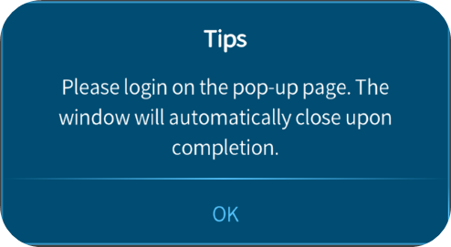
4. Click on the third-party login icon , and click OK in the pop-up prompt window.
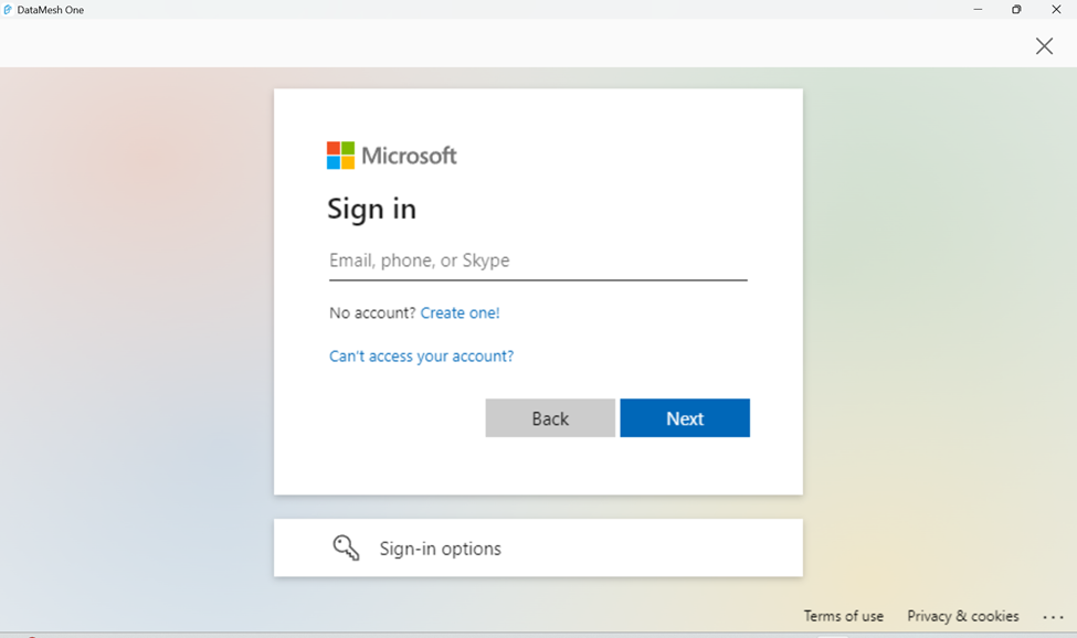
5. Enter Microsoft account and password for logging in.
Scan the code to log in
Using the Scan the code to log in feature provided by the FactVerse Services, quickly log in to your account on DataMesh One.
Steps
1. Open the Login interface of DataMesh One.
2. Select the Language and Server that the enterprise belongs to.
3. If your enterprise has deployed a private server, you must set an exclusive service code before logging in. Please refer to Step 3 in the regular login process for specific setup steps.
4. Click on the scan code icon , and a scanning frame will appear.
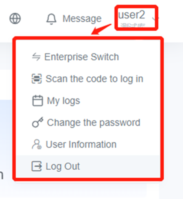
5. Log in to FactVerse Services, click on the username in the top navigation bar, and select Scan the code to log in in the account function menu.
6. The system will automatically generate a QR code that refreshes at intervals.
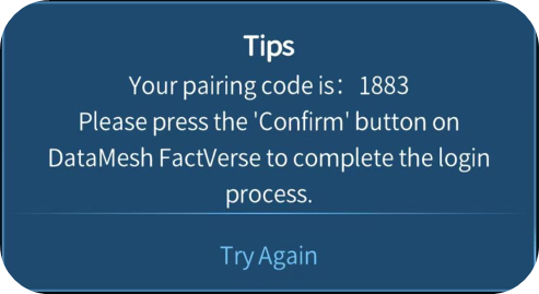
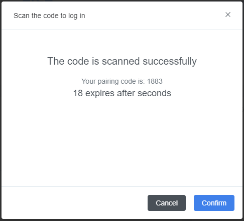
7. Use DataMesh One to scan the QR code generated on the FactVerse Services platform in Step 6. After successfully scanning, a prompt window will appear.
8. In the Scan the code to log in confirmation window on the FactVerse Services platform, click Confirm to complete the login.
The main interface of DataMesh One includes two main modules by default: Resources and Event. Users can switch between them by clicking on the Resources and Event tabs.
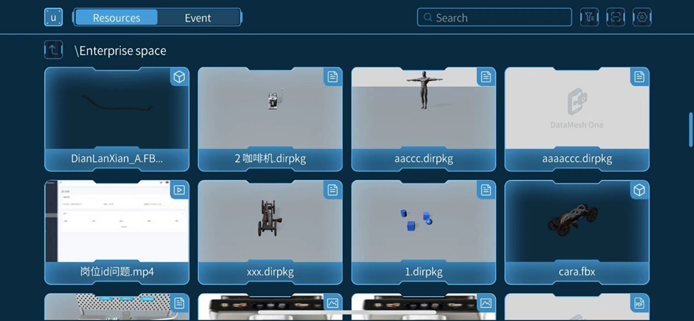
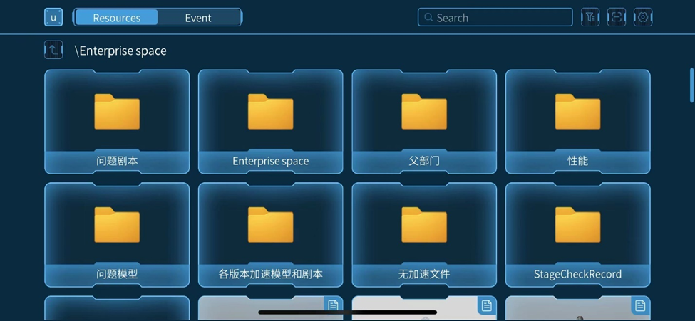
Resources
The Resources interface contains all the folder directories and resource files that the current account has access to. These resource files include 3D models, scenarios, images, PDF files, and more.
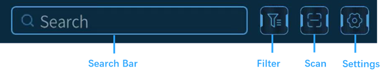
Following figure shows the toolbar of Resources:
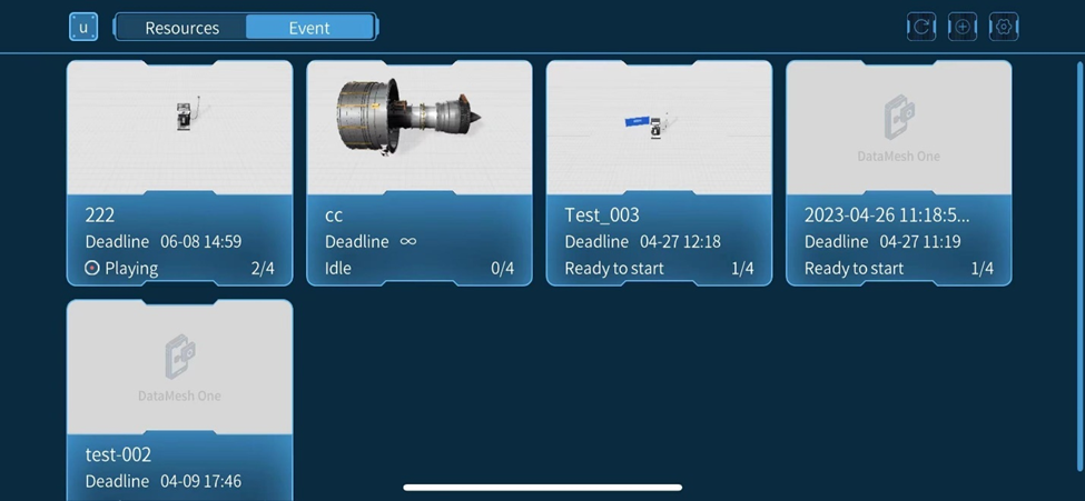
Event
The Event interface is the interface used to manage all the events that the current account has access to. In the Event interface, you can browse the event list, view event details, participant information, and scenarios. If you are the creator of the event, you can also edit the event.
Following figure shows the toolbar of the Event interface:
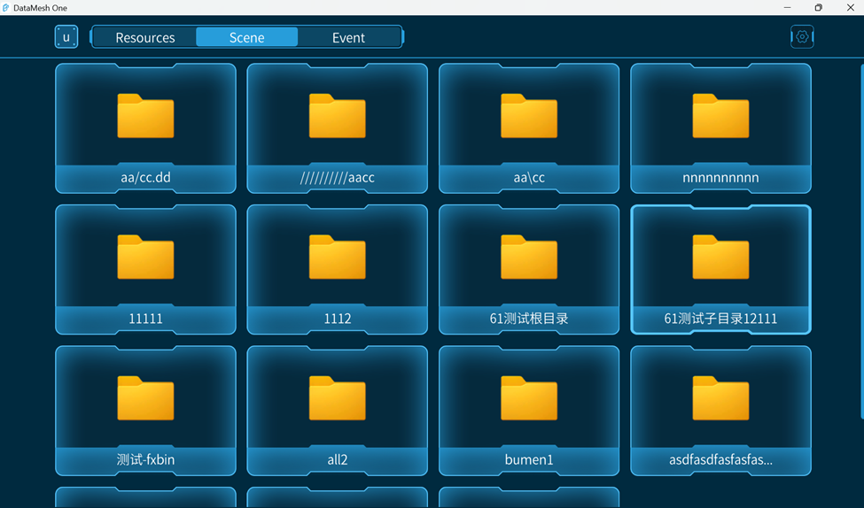
Scene
In DataMesh One, a scene refers to the scene files created by FactVerse Designer. When a user has the permissions for the scene function, that is, the user’s bound position has permissions for the scene function, they can see the scene interface in the main interface of DataMesh One. The scene interface contains all folder directories and scene files in the directory that the current account can access.
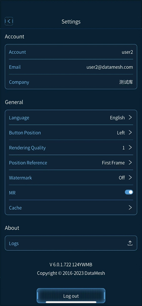
Settings
After clicking the settings button on the Resources or Event interface, you can open the Settings interface. The settings interface includes general settings like account, language, watermark, cache, and features like uploading logs.
Language: DataMesh One supports Simplified Chinese, English, Japanese and Traditional Chinese.
Button Position: You can choose to place the control button on the left or right side of the screen.
Rendering Quality: To adapt to different device performance, DataMesh One provides six different rendering quality options. Increasing the quality can optimize screen aliasing, ripple, and shadow effects.
Position Reference: Position Reference setting aligns the content displayed by DataMesh One in position mode with real-world target objects to achieve positioning accuracy.
Current: Using the current content being played in the scenario as a reference for positioning.
First Frame: Using the first frame of scenario’s first scene as a reference for positioning. For example, a user adds A in the scenario position mode of DataMesh Studio, it will be displayed for positioning under the initial positioning setting.
Watermark: DataMesh One supports turning on/off the watermark. Note: Trial users and demo mode do not support turning off the watermark feature.
MR: DataMesh One supports switching between MR and 3D viewing modes. When using DataMesh One on mobile devices, MR mode is enabled by default, and you can switch to 3D viewing mode by turning off the MR switch in the settings. When using DataMesh One on a PC, only 3D mode is supported, and MR mode is not supported.
Cache: You can choose to clean up all resources or infrequently used resources. Cleaning up infrequently used resource cache will only clear the resource cache that has not been used within 30 days (about 4 and a half weeks). When the system experiences slow performance or other issues, you can try cleaning up the cache to resolve the issue.
Logs: DataMesh One supports uploading the latest seven logs.
Log out: Click the Log out button to log out of the account and return to the login page.
DataMesh One is an application that can be used in conjunction with DataMesh Studio and FactVerse Services platform. It can play immersive 3D data scenarios and display vivid scenes on virtual reality devices, smartphones, tablets, and other devices. In addition, multiple users can share the same 3D space simultaneously, making it convenient for collaborative learning and communication. Our application also provides convenient interactive operations, such as gestures and joysticks, which allows users to interact more organically with models in the 3D space.
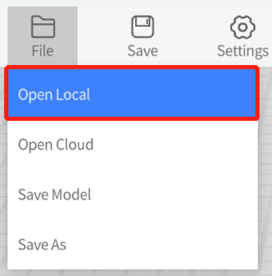
3. Select a local model and click Open in the local resources folder.
Open cloud model
Steps to open a cloud model are as follows:
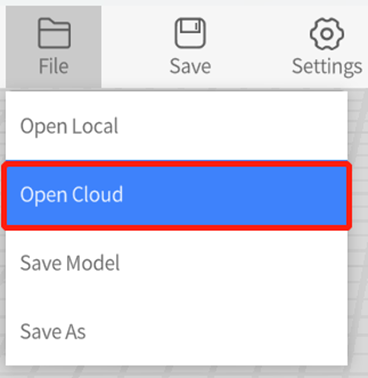
1. Click File menu and select Open Cloud.
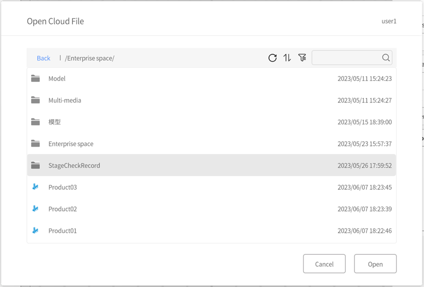
The following figure is the Open Cloud File window:
2. After selecting a model, click Open to open and display the model in DataMesh Importer.
Adjust model material
The material of a model refers to the attributes used to describe the surface characteristics of an object, such as color, reflection, transparency, etc. It determines the appearance and visual effects of the model.
In DataMesh Importer, you can easily modify the material attributes of a model.
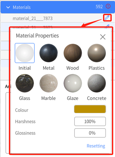
1. Open the model and go to the material list in the attributes pane.
2. Click on the edit button of the material you want to modify.
3. You will open the material properties window, where we provide several commonly used material spheres, including metal, wood, plastics, glass, marble, glaze, and concrete. You can use these material spheres to replace the original material of the model.
In addition, you can use various adjustable properties, including color, transparency, metallicity, and smoothness. These properties can be adjusted separately or in combination, making it easy for you to achieve the desired effect.
Note: When saving the model, the model with modified material will be saved in GLB format to the cloud.
Save model
The steps to save a model are as follows:
1. After opening the model, select the nodes that need to be saved in the left structure directory.
2. In the model attributes area on the right, view the model’s name, platform availability, basic parameters, animation list, and other information. Adjust the model material according to your needs.
3. If the model has not been modified, the Save option in the file menu will be grayed out.
4. If the model has been modified, click File > Save Model or the Save button in the Menus to upload the modified model to the cloud. Note: The original model file in the cloud will be overwritten by the new file.
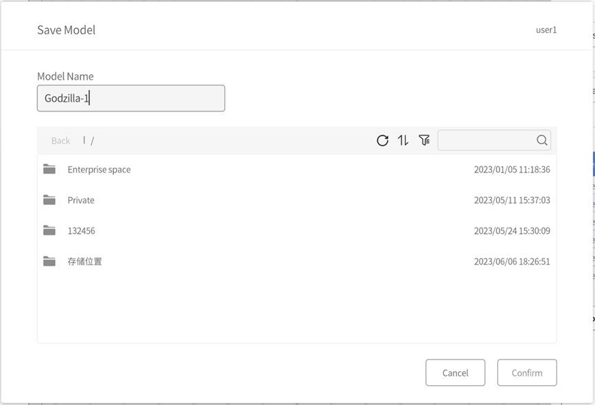
5. In the Save Model window, enter the model file name, select the target path, and click Confirm.
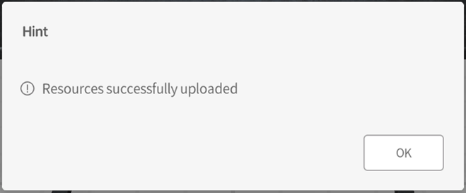
6. Wait for the model to finish uploading, and the page will prompt that “Resources successfully uploaded”.
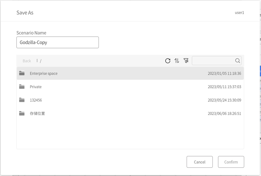
Save as
In DataMesh Importer, you can save the imported model as a new file by following these steps:
1. Click the File menu and select the Save As option.
2. In the pop-up Save As window, choose the path and file name for saving the model.
Note: You should avoid using the same file name as the model file in the cloud. It is recommended to choose a different file name or select a different folder in the same path when saving the model.