How Can We Help?
Interaction position and assessment
When you have a DataMesh Learn license, you can use the location position and assessment features in DataMesh Studio to create training and assessment scenarios.
You can set up user interactions with the scenario by adding link actions or interaction position to characters, thus creating scenarios with assessment tasks and scoring. Through these interactive actions, users can complete assessment tasks, and their performance can be evaluated and assessed based on their actions.
Set Target Location
This feature allows you to assess the viewer’s ability to move an element from a starting location to a target location while viewing the scenario in mixed reality, which can simulate machine assembly, disassembly, repairs, and more.
Add an interaction position
In DataMesh Studio, you can add interaction positions for models and tools, and configure relevant parameters to achieve precise interaction effects, such as initial position, target position, tolerance angle range, automatic attraction range, etc.
The steps to add interaction positions to elements are as follows:
1. Select the element, then press the white Set Interaction Position button in the attributes pane.
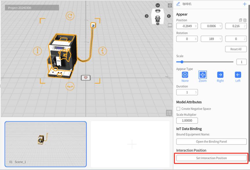
2. A prompt should appear at the top of the workspace, which signifies that you have entered interactive building mode. From here, you can drag, rotate, and resize the model into your desired target location.
3. Users can set the interaction position in the attributes pane. For example, customize the interaction name, set the target position of the element, etc.
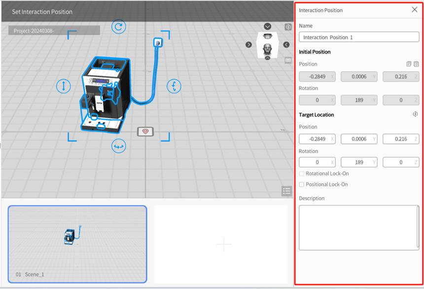
The Interaction pane is shown in the figure below:
-
- Name: This is the name of the interactive position, which can be viewed from the Scene Attributes pane.
- Initial Position: This parameter shows the starting position and rotation of the element and is grayed out during target mode. To change the initial position, exit target mode to move the element, then return to target mode.
- Target Location: This parameter shows the coordinates and rotation of the target location. You can change this by dragging and rotating the model in the workspace, or by manually inputting the values.
- Rotational Lock-on: This is an optional parameter that allows you to configure how similar the angle of the element needs to be to the target location in order to lock into place.
- Positional Lock-on: This is an optional parameter that allows you to configure how far away the element needs to be from the target location in order to lock into place.
4. Click ![]() on the top corner of the Interaction pane, click YES in the popping up box to save the operation.
on the top corner of the Interaction pane, click YES in the popping up box to save the operation.

Check the interaction position list
Click on the workspace and then select the Interaction dropdown icon in the scene, all the interaction positions within the scene will be shown in the attributes pane.

The interaction position list is arranged in ascending order of creation time, displaying interaction order, name, description, and operations.
Operations supported by the interaction position list:
1. Delete: Press the trash can icon to remove the interaction.
2. Move up or down: Click the up or down icons to change the order of interactions.
3. Edit: Click interaction name to enter interaction edition mode to edit the position interaction.
Task
A task refers to a specific objective that scenario editors can set for viewers in order for them to progress through the scenario. Tasks can be used to guide viewers through a simulated workflow, test viewers to see what they would do during certain situations and evaluate their performance. You can also set task categories in order to test for different criteria, and you can set numerical score values for each task in order to quantitatively assess the effectiveness of each viewer.
Create a task category
The steps for creating task categories are as follows:
1. Click Assessment in the Menu and then select the Task option. In the toolbar, go to Assessment > Task.
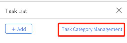
2. In the Task List, click the Task Category Management link in order to manage your categories.
3. In the Task Category List, click the Add button to open the Task Category window.

4. In the pop-up window, set the parameters of your new type. Below is an explanation of each parameter.
-
- Category Name: Enter the type name here. Each task that belongs to this category will display a label containing this name in the task list. The character limit is 18, with no restriction on character format.
- Label Color: This changes what color the type label is. Changing this allows you to easily differentiate between categories in the task list. The default color is red.
- Total Available Points: This allows you to set the maximum score a viewer can earn for this category.
- Passable: If this option is enabled, you could enter a passing grade to easily see if viewers passed or failed in this category.
5. Click Confirm to add your new category.
Create a task
The steps to create a new task are as follows:
1. In the toolbar, go to Assessment > Task.
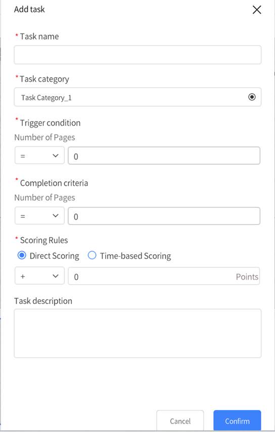
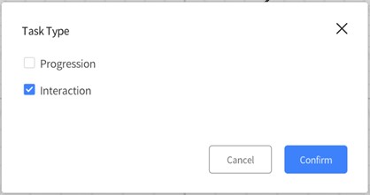
2. In the Task List, click the Add button to open the Task Type window.

DataMesh Studio provides two task types for you to select:
-
- Progression: This type of task scores the viewer based on their progression through the scenario. This is effective when utilized in choice-based scenes that navigate to other scenes based on the viewer’s choice.
-
- Interaction: This type of task scores the viewer based on performing the correct actions in each scene. This is effective when utilized in hands-on scenes where the viewer must place a component in the correct location.
Scenario play mode
When a scenario is created with the purpose of testing viewers, some scenarios can have a linear progression through their scenes, while others may need to jump around between scenes using the link action. The navigation window allows you to control how viewers are able to navigate between scenes, ensuring that they cannot skip forwards or backwards in an unintended order.
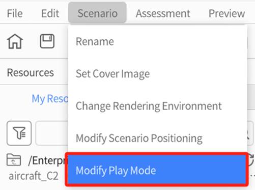
To modify the scenario playback mode, you can click on the scenario menu, select Modify Play Mode.
In the window of Modify Play Mode, check or uncheck the option for “Enable Stage Traversal” as needed. When this option is checked, you can navigate scenes by clicking the page turn button while playing the scenario in DataMesh Learn.
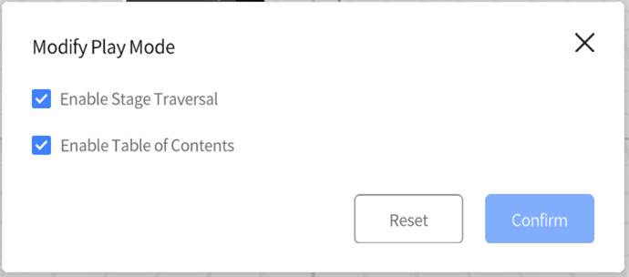
Enable Stage Traversal: If this option is enabled, viewers can freely travel to the next scene whenever they want. Disabling this option ensures that they have to fulfill any conditions you have set before moving forward.
Enable Table of Contents: When this is enabled, viewers can see the table of contents, and select any scene that it contains in order to travel to that scene.
Exercise: Create a Graded Scenario About Assembling Cable Lines
Objective
The training instructor can use DataMesh Studio to create a scenario for assembling cable lines that includes task assessment and scoring.
Prerequisite
The cable line models (DianLanXian_A, DianLanXian_B, CRMA15_Xian) and the cable interface models (DianLanJieKou, CRMA16_JieKou) have been uploaded to the resource library of FactVerse Services.
Steps
1. From the Resources pane, add all the necessary models into the workspace.

2. Add interaction position for cable line DianLanXian_A.
a). Select the cable line “DianLanXian_A” in the element list and click the Set Interaction Position button in the attributes pane.
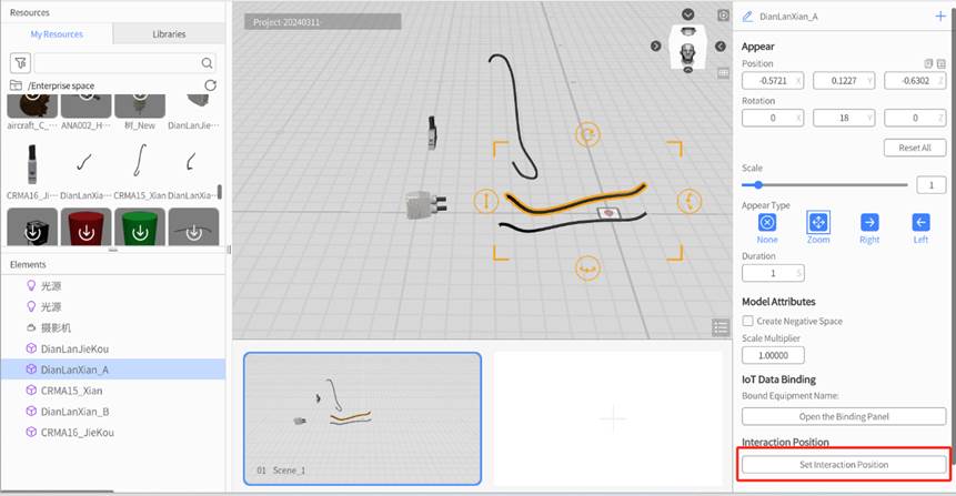
b). In the Interaction pane, change the interaction Name to “Cable Line A Position Interaction”.
c). Move the cable line to the cable interface location in the scene and set the target position for the cable line.
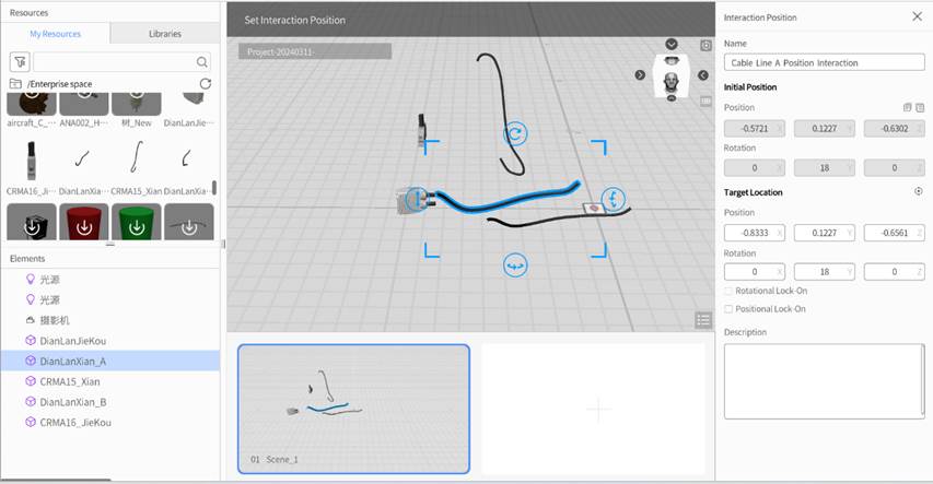
d). In the Interaction pane of the attributes pane, set the Positional Lock-on to “1” (unit: m).
e). Move the cable line to the cable interface location in the scene and set the target position for the cable line.
3. Add interaction position for cable line DianLanXian_B.
a). Select the cable line “DianLanXian_B” in the element list and click the Set Interaction Position button in the attributes pane.
b). In the Interaction pane, change the interaction Name to “Cable Line B Position Interaction”.
c). Move the cable line to the cable interface location in the scene and set the target position for the cable line.
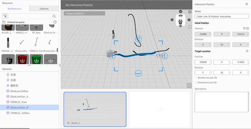
d). In the Interaction pane of the attributes pane, set the Positional Lock-on to “1” (unit: m).
e). Click x button to exit the Interactive Build mode, in the pop-up prompt box, click the Yes button to save the operation.
4. Add position interaction for cable line CRMA15_Xian.
a). Select the cable line “CRMA15_Xian” in the element list and click the Set Interaction Position button in the attributes pane.
b). In the Interaction pane, change the interaction Name to “Cable Line C Position Interaction”.
c). Move the cable line to the cable interface location in the scene and set the target position for the cable line.
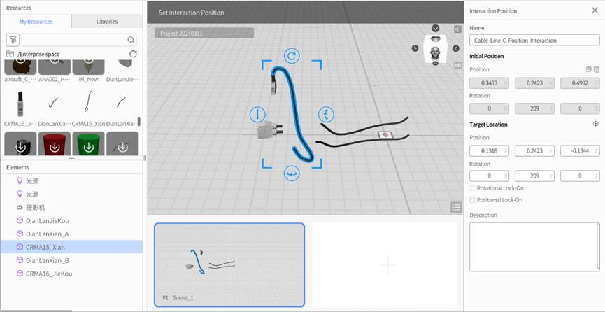
d). In the Interaction pane of the attributes pane, set the Positional Lock-on to “1” (unit: m).
e). Click x button to exit the Interactive Build mode, in the pop-up prompt box, click the Yes button to save the operation.
5. Click anywhere in your workspace that does not select a an element, and the attributes pane will display the list of interaction positions in the scene.

6. Create a task type.
a). Click on the Assessment menu in the Menu, and then select the Task
b). In the Task List of the attributes pane, click on the Task Category Management to open the Task Category List.
c). In the Task Category List, click the Add button to open the Task Category window.
d). In the Task Category window, enter the task Category Name as “Interaction” and select the necessary parameters such as Passable and Passing Score.
e). Click Confirm to complete the addition of the task category.
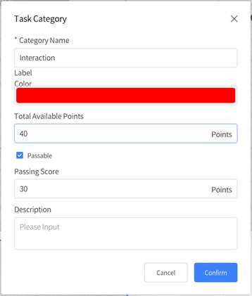
f). Click < to exit the Task Category List.

7. Create a new scoring task.
a). In the Task List pane, click the Add

b). In the Task Type window, select Interaction and click Confirm
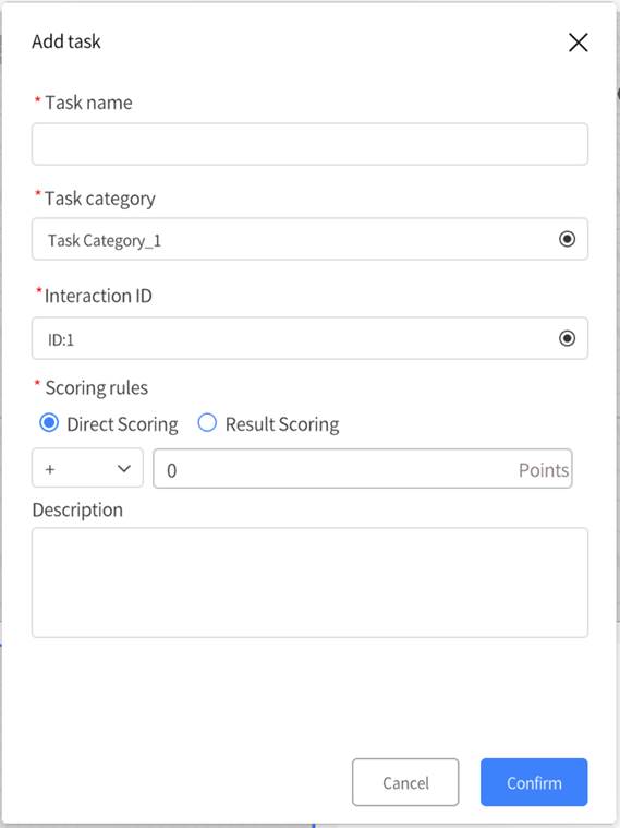
c). In the Add task window, fill in Task name as “Assemble Cable Line with Cable Interface”.
-
-
- Select Task type as “Interaction”.
- Selection Interaction ID as “ID:2”.
- Set Scoring rules as Result Scoring, Operation succeeded as + 20 scores.
-
d). Click the Confirm button to complete the addition of the task.

8. Click ![]() in the toolbar to view the real effect.
in the toolbar to view the real effect.
a). Click in the toolbar to view the real effect.

b). Click the Complete

c). After demonstrating all the interactions, you can click the Skip button to enter the next scene.
9. Click Modify Play Mode in the Menu and uncheck the option Passable.
10. Save the scenario with the name “Assembling Cable Lines”.