How Can We Help?
Digital Assets
The module of digital assets covers Resources, Digital Twins, and BIM Data.
Directory management of digital assets
In the Digital Assets module, the directory is a key tool for managing digital twin assets and resources. The directory bar displays all the directories that users can access, making it convenient for users to manage digital twin assets, resources, etc.

The directory provides rich management functions:
- Create a new directory: Users can create new directories as needed and define who is visible to these directories.
- Delete directories: Users who possess deletion permission can delete customized public directories to better organize and manage digital assets.
- Directory sorting: Provides sorting functions by modification date, creation date, name, etc., supporting both ascending and descending order.
Directory type
The digital asset directory is divided into the following four types:
|
Type |
Description |
|
Department directory |
With the creation of departments, the system will automatically establish corresponding directories for the unified organization and management of departmental data and resources. Department directories will be automatically deleted when departments are deleted. |
|
User personal directory |
Personal storage space, named “My Space”, accessible and viewable only by the user themselves. |
|
Public directories created by users |
They are established by users with the permission to create new primary directories and are suitable for resource sharing and collaboration. |
|
DLC resource directory |
Public Directory and its subdirectories store digital twin resources launched by DataMesh. In the Resources, the DLC resource directory contains DLC model resources; in the Digital Twins, the DLC resource directory contains digital twin templates, digital twins, scenes, and attribute groups. |
User permission
Explanation of permissions in the chart:
- ✅: Granted permission
- ❌: No permission
Department directory permission
|
Operation |
Regular User |
Administrator |
|
View directory |
✅ |
✅ |
|
Create subdirectories |
✅ |
✅ |
|
Resources management |
✅ (View, upload, download, edit, move) |
✅ (View, upload, download, edit, move) |
|
Create department directory |
❌ |
✅ (Automatically create via the creation of department) |
|
Delete department directory |
❌ |
✅ (Automatically delete via the deletion of department) |
DLC resource directory permission
|
Operation |
All users |
|
View directory and resources |
✅ |
|
Use resources (eg. Use models in the DLC to edit scenario) |
✅ |
|
Delete resources |
❌ |
|
Delete directories |
❌ |
User personal directory permission
|
Operation |
Individual users |
|
View directory and resources |
✅ |
|
Create subdirectories |
✅ |
|
Manage resources |
✅ |
Permission for public directories created by users
|
Operation |
Creator |
Users visible to the directory |
Company administrator |
|
View directories |
✅ |
✅ |
✅ |
|
Edit visibility |
✅ |
❌ |
✅ |
|
Add subdirectories |
✅ |
✅ |
✅ |
|
Delete directories |
✅ |
❌ |
✅ |
|
Manage resources |
✅ |
✅ |
✅ |
Note: Deleting a directory will automatically delete its subdirectories.
Resource locking mechanism
To maintain resource consistency and data security in a collaborative multi-user environment, the FactVerse platform supports a resource locking mechanism. The following types of resources can be locked:
- Scenario
- Scene
- Template
- Behavior tree
Locking rules:
- Exclusive editing on one device: Each resource type can only be edited by one user on a single device at a time. It cannot be accessed simultaneously by multiple users or devices.
- Lock status indicator: When a resource is in use, a lock icon
 will appear next to it, showing that it is currently being edited.
- Manual unlocking: If a resource remains locked for an extended period due to issues like network interruptions or program crashes, the creator or current editor can click the lock icon to manually unlock the resource, releasing it and restoring editing access.
Resources
The Resources includes documents, images, videos, audio files, models uploaded by users, as well as scenario files created by DataMesh Studio. Users can load and use files from the Resources in DataMesh client products.
You can select Digital Assets > Resources in the functional module navigation bar to enter the resources page. The resources page supports operations such as uploading and downloading resource files.
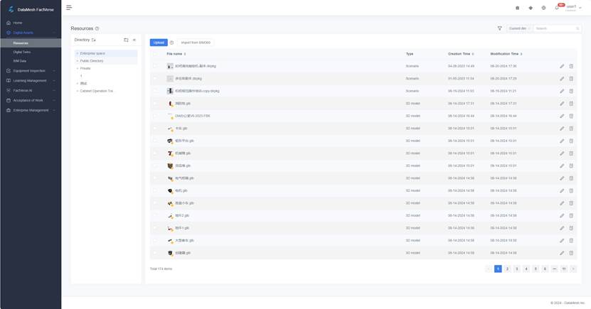
Below are the operation instructions for the Resources page:
- Upload resources: On the Resources page, you can click the upload button
 to upload your resource files. For more information about uploading resources, please refer to Upload Resources.
- Filter resources: Click
 to filter resources by tags and types.
- After selecting a tag, the resource list will display all resources with that tag.
- You can view resources by type, including scenario, model, and document.
- Resource search: You can use the search box to search for resources, and the search location option before the search box allows you to choose whether to conduct a global search or a search in the current directory.
- Resource operations: After selecting a resource file, you can choose to download, delete, or move the resource file. Note: When the user does not have operation permission, the operation option button is grayed out.

- View resource details: Click the resource details button
 to view resource file details.
 - Rename resource files: Click the resource’s edit button
 , you can rename the resource.
View resource details
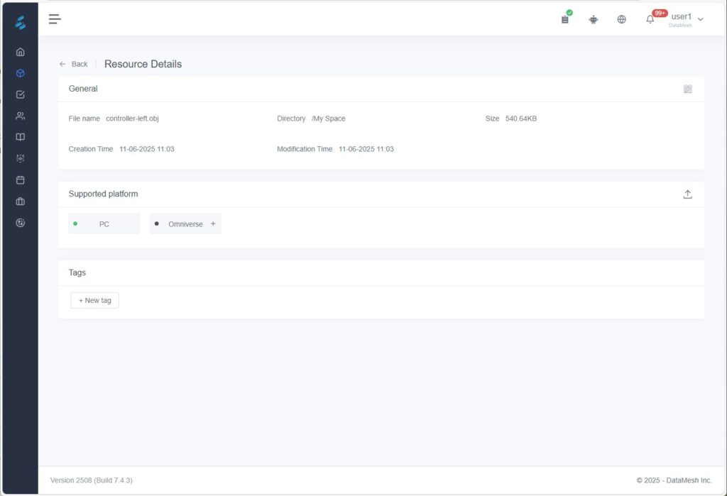
To view a resource’s details, navigate to its directory on the Resources page and either click the resource name or the details icon![]() . This opens the Resource Details page, which displays metadata, tags, and—for 3D models—additional compatibility information.
. This opens the Resource Details page, which displays metadata, tags, and—for 3D models—additional compatibility information.
|
Field |
Description |
|
File Name |
The name of the uploaded file. |
|
Directory |
Where the resource is stored in the platform. |
|
Size |
File size. |
|
Created Time |
When the resource was uploaded. |
|
Modification Time |
Most recent update time. |
|
Number of markers |
Number of locators used in the script (shown only for script-type files). |
|
Tags |
Used for classifying and filtering resources, activities, and scenes. |
|
QR Code |
Click the QR Code icon |
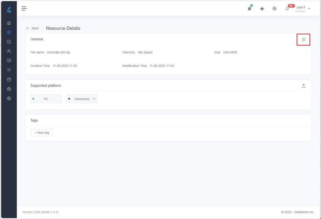
Supported Platform
If the resource is one of the following model formats: .glb, .fbx, .3mf, .obj, .ply, or .stl, you’ll also see the following fields:
|
Field |
Description |
|
Omniverse Binding |
Use the Omniverse+ button to bind or replace a .usd / .usdp file for Omniverse collaboration. |
|
Accelerated Platforms |
Shows platforms (e.g. iOS, macOS) where acceleration attachments have been added. Visible only for older models or if attachments were manually uploaded. |
|
Upload Acceleration File |
Click the Upload icon |
Notes:
- Models in the Public Directory (DLC) are maintained by the official DataMesh account and cannot be modified by any user, including admins.
- Starting from FactVerse 7.4.2, automatic acceleration has been deprecated. Use the latest DataMesh Importer (with experimental features enabled) to upload models for auto-optimization.
- For older models, models imported from legacy projects, or uploads that load slowly, manual acceleration file upload is still supported.
Upload resources
You can upload different types of files to the DataMesh FactVerse platform, each with its respective size limit.
|
File Type |
File Extension |
Size limit |
|
Document |
|
256MB |
|
Video |
.mp4, .mov |
256MB |
|
Audio |
.mp3, .ogg |
256MB |
|
Image |
.png, .jpg |
128MB |
|
3D model |
glb, fbx, 3mf, obj, ply, stl, rvt |
500MB |
|
Simulation data script file |
.iotsim |
128MB |
|
Customizable resources |
.zip |
128MB |
Upload customizable resources
Customizable resources include advanced resources, tools, and personalized scenes that typically require development support from DataMesh to achieve specific functions or effects.
Upload Method
Use DataMesh Importer to upload a ZIP package of the customized asset to the FactVerse platform:
- If experimental features are enabled: the ZIP will be automatically unpacked and displayed as a .dmasset file.
- If not enabled: the file remains in ZIP format after upload.
Upload documents, videos, audio, images, 3D models, data script files
You can upload various types of files—such as documents, videos, audio, images, 3D models, and data scripts—and store them in your designated directories as needed.
⚠️ Note: For 3D models, it is highly recommended to upload them using DataMesh Importer. This ensures better loading performance and allows you to adjust material properties, helping improve the model’s quality and future usability.
Steps
The steps for uploading resources are as follows:
1. Select the directory where you want to store the resource on the Resources page, and then click the Upload button.
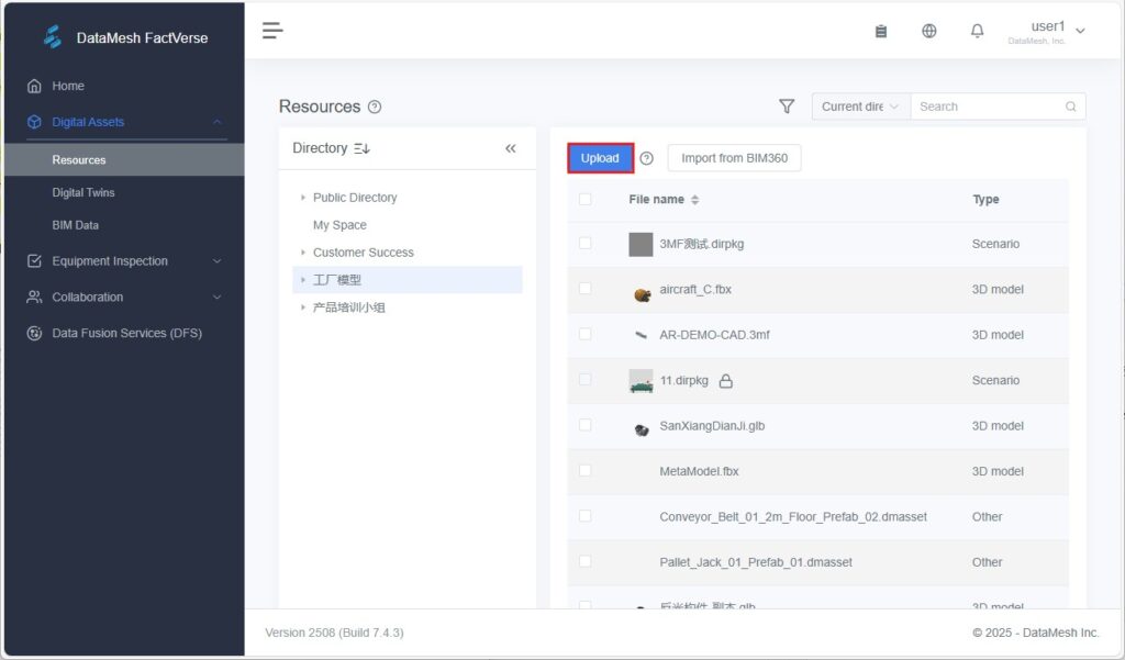
2. Click ![]() or drag files to the upload window. You can upload up to 10 files at a time.
or drag files to the upload window. You can upload up to 10 files at a time.

3. Click the Upload button to start uploading files.
4. Click the Upload details button on the top navigation bar to view upload details of the files.
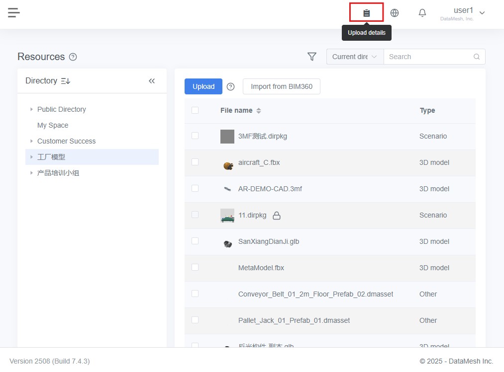
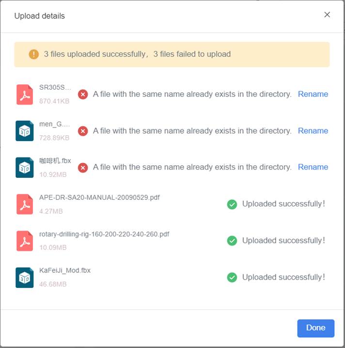
If a file being uploaded has the same name as a file in the directory, it will result in an upload failure. You can rename the file in the Upload details window and then upload it again.
5. Once the upload is complete, the file will appear in the designated folder within the Resources Library.
Uploading Acceleration Files
To improve model loading performance across different platforms, you can upload acceleration files for the following types of models:
- Models uploaded directly via the FactVerse platform
- Models uploaded via DataMesh Importer without enabling the Experimental Features
- Models created through “Import Scenario/Scene” or similar features
⚠️ If the model was uploaded via Importer with Experimental Features enabled, the new loading mechanism is applied automatically, and the acceleration upload option will not appear.
How to Upload
1. Obtain the Acceleration File
Contact DataMesh technical support to get the corresponding acceleration files for your models.
2. Go to Model Details
In the FactVerse Resources page, locate your model file and open its detail page.
3. Open the Upload Window
Under Supported Platforms, click the upload icon to open the upload window.

4. Upload the Acceleration File(s)
Click the area or drag files in.
- Up to 8 files can be uploaded at once
- File naming format: [ModelName]_[Platform].ab
- Re-uploads will overwrite existing files for that platform
Supported Platforms:
PC, UWP, Android, iOS, macOS, WebGL
5. Verify Upload
After successful upload, the corresponding platform tag will appear under Supported Platforms, indicating acceleration is active for that platform.

Notes
- Acceleration files help improve loading performance in both Studio and One.
- If the model is used in a script or scene, remember to include acceleration files when exporting.
- ⚠️ Uploading mismatched files (e.g., uploading an A model’s file to model B) can cause loading issues. Please double-check filenames before uploading.
Import files from BIM 360
The DataMesh FactVerse platform supports importing files from Autodesk BIM 360.
Prerequisites: The administrator has configured the Autodesk BIM 360 account in the enterprise settings.
Steps for importing files from BIM360:
1. Select the directory in the Resources page to store the resources, then click the Import from BIM 360 button.

2. In the Hub window, select the BIM360 account, then click Confirm.
3. In the Project window, select the project and click Confirm.
4. In the Folder window, select the folder, then click Confirm.
5. In the project window, select the .rvt file to upload, then click Confirm to complete the file import.
Delete resources
You can delete one or more resource files at once. Here are the steps to delete a resource:
1. Select the directory where the resource is located on the Resources page, and then check the checkbox in front of the resource file you want to delete.
2. Click the delete button ![]() .
.
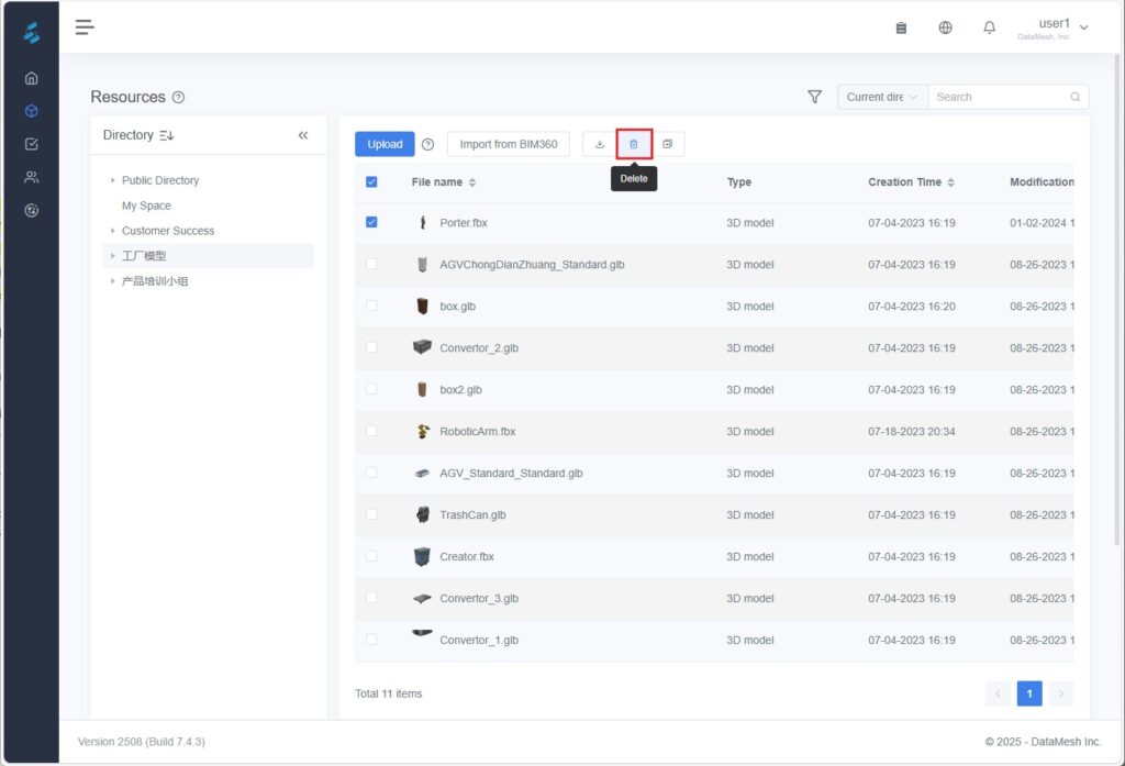
3. Click Confirm in the pop-up prompt window to complete the resource deletion.
Note: Deleted files cannot be recovered and will cause scenarios that use these files to be unable to play. Therefore, please make sure that you no longer need these resource files before deleting them.

Download resources
To download resources to your local device:
1. Select the directory where the resource is on the Resources page and check the checkbox in front of the resource file you want to download.
2. Click the Download button ![]() .
.
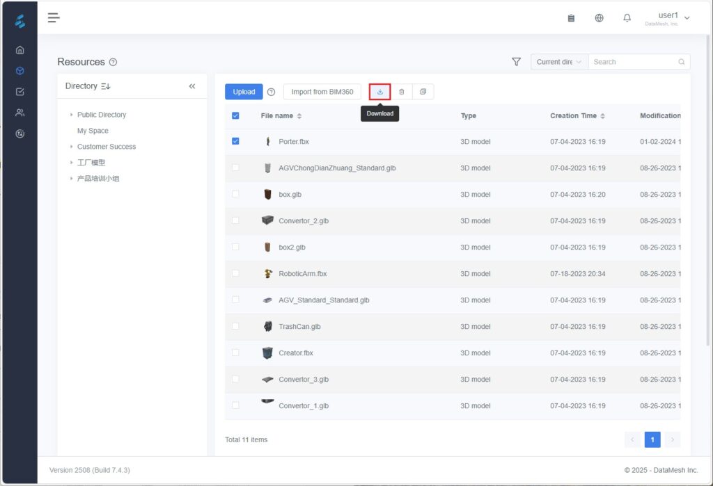
3. When the browser prompts you to download multiple files, you need to click Allow to complete the download of multiple resources.
Move resources
To move one or more resource files to another storage directory:
1. Select the directory where the resource is on the Resources page and check the checkbox in front of the resource file you want to move. If you want to move multiple files, you can select multiple checkboxes.
2. Click the Move button ![]() .
.
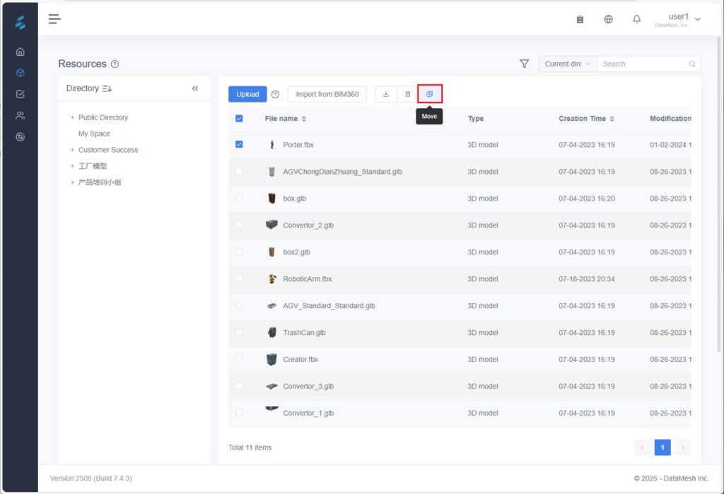
3. In the pop-up window for selecting the directory, select the target folder directory where you want to move the resource.
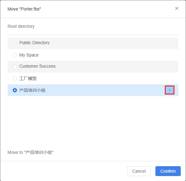
4. Click the Confirm button to confirm your selection, and the system will move the selected resource files to the target folder.
Rename resource files
To rename a resource file:
1. Select the directory where the resource is located on the Resources page.
2. Click the edit button ![]() of the resource.
of the resource.
3. Modify the resource name.

4. Click the Finish button ![]() to complete the resource renaming.
to complete the resource renaming.
Bind USD files (for Omniverse rendering)
To ensure 3D model resources in FactVerse are recognized and rendered by NVIDIA Omniverse, the model must be linked to a USD file (in .usdz or .usdp format), which is the standard format supported by Omniverse.
Supported Model Formats
|
File Format |
Extension |
Description |
|
GLB |
.glb |
A binary format widely used for real-time 3D rendering |
|
FBX |
.fbx |
Commonly used for animation and model exchange |
|
3MF |
.3mf |
A 3D printing format that supports color and material information |
|
OBJ |
.obj |
A generic 3D geometry format |
|
PLY |
.ply |
Used for 3D scan data with attribute support |
|
STL |
.stl |
A geometry-only format used for 3D printing |
Note: Binding USD files is not supported for models of downloadable content (DLC) provided by DataMesh.
Steps
1. Prepare the USD File: Choose the file format based on project requirements.
a) .usdz format: Use the model conversion tool provided by DataMesh to convert formats like GLB, FBX, etc., to .usdz files. For detailed steps, refer to the section Upload USD model resource.
b) .usdp File: Contains the model’s animations, textures, materials, and other resources. Contact DataMesh for assistance in generating this file.
2. Bind the .usdz file to the model resource
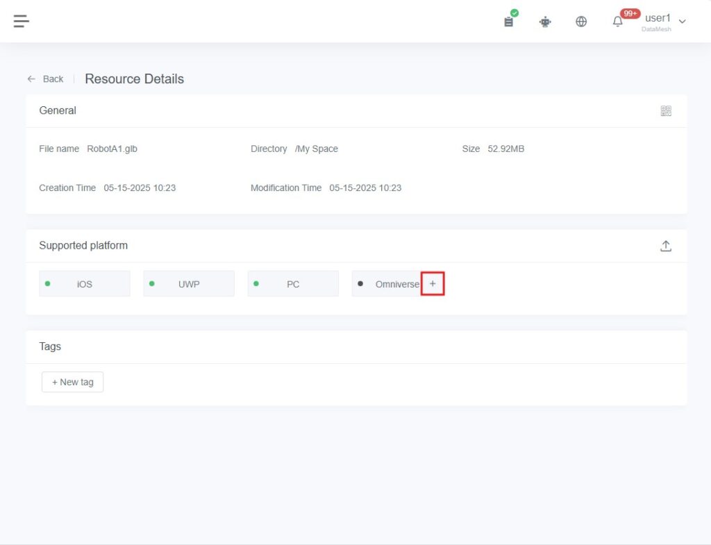
a) Go to the Resource Details page for your target asset.
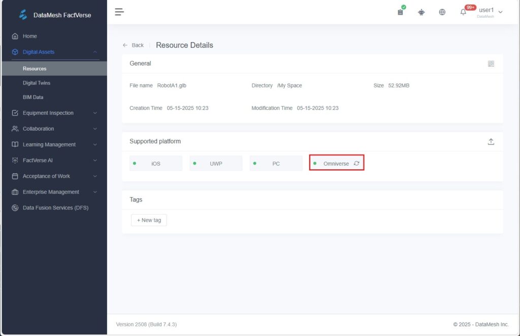
b) In the Supported Platforms section, click the “+” icon next to the Omniverse.
c) In the pop-up window, either open the resource folder or drag and drop the .usdz / .usdp file into the upload area. Each model can only have one USD file bound.
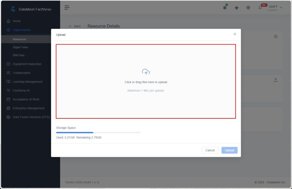
d) Click Upload to complete the binding.
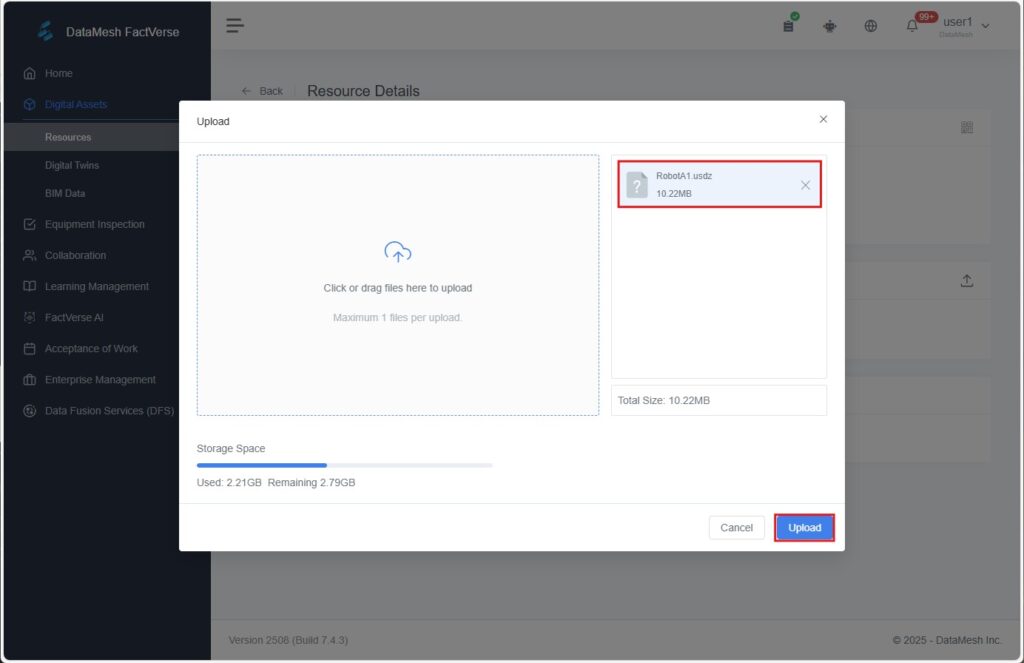
Once uploaded successfully, you’ll see a “Uploaded successfully” message, and the icon to the left of the Omniverse button will change to a green dot.
To update the file, simply click the refresh icon and re-upload a new .usdz file.
Before importing a digital twin scene via the FactVerse Omniverse Adaptor and enabling data-driven interactions, ensure all models are properly bound with .usdz files to guarantee correct rendering in Omniverse.
For more details, please refer to FactVerse Omniverse Adaptor User Guide.
Digital Twins
You can navigate to the Digital Assets > Digital Twins in the function module navigation bar to access the Digital Twins page.

On the Digital Twins page, you can centrally manage all digital twin-related resources, including:
- Create resources: Click the New button to create a new template, digital twin, scene, or attribute group.
- Filter and sort: Click the Filter icon
 to narrow down your resources based on the following criteria:
- By Tag: Filter resources that contain specific tags.
- By type: Browse by types such as “Template,” “Digital Twin,” “Scene,” “Behavior Tree,” or “Attribute Group.”
In the Digital Twin type, you can also filter by usage status:
-
-
- In Use: The digital twin has been referenced in a scene.
- Not Used: The digital twin has not been referenced in any scene.
-

- Search resources: Enter keywords in the search box to find resources. You can toggle the search scope between global search and search within the current directory.
- Bulk actions: Check the boxes next to resources to perform bulk actions like Delete or Move.
- View details: Click on a resource name or the Details button
 to view more information about the resource.
Template
A digital twin template defines a category of digital twins, a template for describing a category of digital twins. Each template contains metadata, behavior trees, and models for a category of digital twins, supporting the creation of similar digital twins.
Create a new template
On the Digital Twins page, you can create a blank template to start defining your digital twin.
Here are the steps to create a new template:
1. Select the storage directory for the template on the Digital Twins page.
2. Click the New button.

3. In the New digital twin window, select the Template section.

4. In the New Template window, fill in the template information and click the Confirm button.
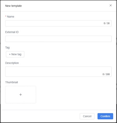
- Name (required): The name of the twin template. It must start with Chinese, Japanese, English, or numbers, and up to 30 characters.
- Tags: Users can customize tags for template classification.
- Description: Template description.
- Thumbnail: Template cover image.
View template details
On the template detail page, you can view and manage detailed information about the template, including attribute groups, behavior trees, resources, sub-templates, and the digital twins that reference the template.
Steps
1. Select the storage directory for the template on the Digital Twins page.
2. Click the template name or the Details icon ![]() on the right to enter the Template details page.
on the right to enter the Template details page.
3. On the Template Details page, you can view template information and perform the following actions:
- Add/manage attribute groups (including private and public attribute groups)
- Add behavior trees, resources, or sub-templates
- View the digital twins created using this template

Add a private attribute group
Private attribute groups allow you to add a custom set of attributes to a template. These attributes apply only to the current template and enable personalized extensions.
Steps:
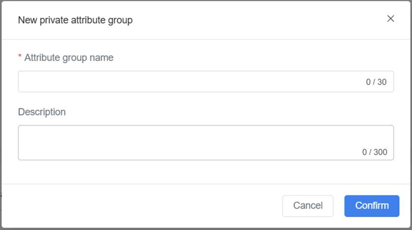
1. On the Template Details page, go to the Attributes tab and click the New button.
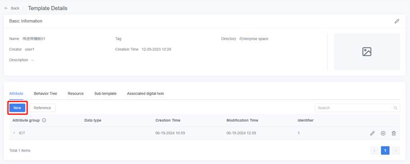
2. In the pop-up window, enter the attribute group details and click Confirm. The new attribute group will appear in the attribute group list.
3. Click the add button ![]() of the attribute group.
of the attribute group.

4. Fill in the basic information for the attribute. For the data type, refer to the section Data types of attributes.

5. Click Confirm to complete the creation of the attribute.
6. You can repeat Step 3 to Step 5 to create more attributes.
Reference the public attribute group
Referencing an existing public attribute group allows you to quickly reuse standard attribute sets, streamlining the configuration process.
Prerequisites:
1. The required public attribute group has already been created (by the current user or another user with the appropriate permissions). For more information on creating public attribute groups, please refer to Create a public attribute group.
2. The current user has permission to access the directory where the attribute group is stored.
Steps:
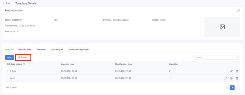
1. On the Template Details page, go to the Attributes tab and click the Reference button.
2. In the pop-up window, enter the Attribute group name, select the target directory, and select the public attribute groups you want to reference.
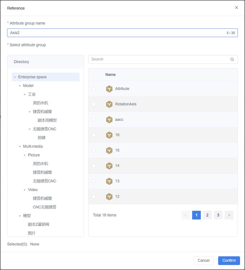
3. Click Confirm, and the referenced attribute group will appear in the list with the format “✩Attribute Group Name.”
Add sub-templates
Sub-templates are used to build more complex template structures, such as adding a “Tire Template” as part of an “Autonomous Vehicle Template.”
Steps:
1. On the Template Details page, go to the Sub-template tab and click the Select.

2. In the pop-up window, check the sub-templates you want to add.
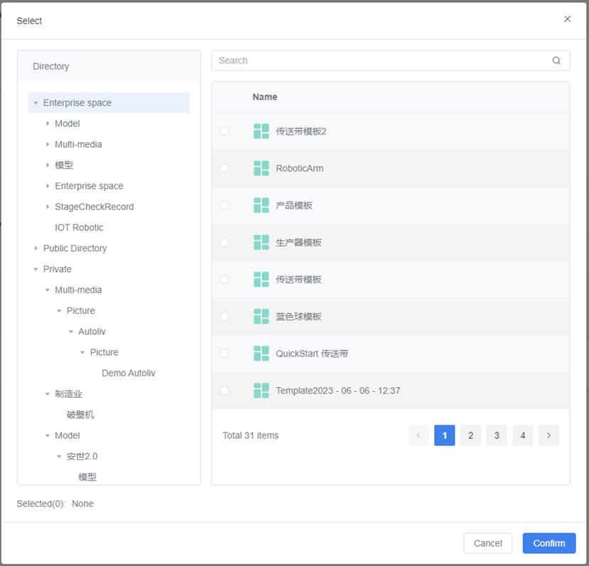
3. Click Confirm to complete the addition of the sub-template.
Delete a template
You can delete unnecessary templates by following these steps:
1. Select the storage directory for the template on the Digital Twins page.
2. Click the delete button ![]() of the template you want to delete.
of the template you want to delete.

3. In the prompt window, click Confirm.

Attribute Groups
An attribute group is a collection of common attributes used to describe a digital twin, which usually correspond to the functionality, characteristics, or information of the digital twin.
You can manage public attribute groups in the Digital Twins page and reference these attribute groups in templates when needed to quickly add attribute groups and improve their reusability and maintainability.
Data types of attributes
Attributes are used to describe the properties or characteristics of a digital twin, which usually correspond to the functionality, characteristics, or information of the digital twin.
The following table shows the data types of attributes used in FactVerse:
|
Type |
Description |
Definable attributes |
|
Int |
Integer type, used to describe integer physical quantities, such as 1, 2, 5.
|
Quantity, frequency, speed, etc. |
|
Double |
Describes physical quantities in floating-point format, with 8-byte precision, such as 1.2, 2.5, 3.0. It can be used to represent attributes that require precise numerical representation, such as “time”, “percentage”, and “exchange rate”.
|
Temperature, humidity, power consumption, balance, mass, area, etc. |
|
String |
Also known as a text type, used to input text. Data length: The default set value is 10240 bytes. |
ID, model, etc. |
|
Bool |
Also known as the Boolean type, it is a judgment type used for logical judgment. The value of a bool type attribute is either true (1) or false (0). |
Operational status, check status, execution results, etc. |
|
Vector3 |
Used to describe physical quantities of three-dimensional space information, such as coordinates, rotation angles, scaling, and other attributes.
|
Placement position, placement angle, path positions, etc. |
|
Color |
Color format: The format is R, G, B, A. The first three numbers represent the RGB color values, and the fourth number represents the transparency value. |
Appearance colors, status colors, etc. |
|
Path |
0:x,y,z or 1:x,y,z, where 0 represents a straight line and 1 represents a curve. The coordinates of two points are separated by the “|” symbol. For example, 0:0,1,0|0:5,1,0 represents a straight path between the points (0,1,0) and (5,1,0). |
Moving paths, transfer paths, transport paths, etc. |
|
Date |
Date format: YYYY-MM-DD, for example, 2024-08-09 |
Production date, maintenance date, etc. |
|
Time |
Time format: HH:MM:SS, for example, 14:30:00 |
Start time, landing time, stop time, etc. |
|
Enum |
Enum type format: A predefined list of values, for example: [01, 02, 03]. |
Error codes and error types, product codes and product categories, etc. |
|
Vector2 |
Used for 2D coordinates or vectors (x, y) |
Example use cases: planar positions, UI element locations |
|
Object |
General-purpose object type for encapsulating complex data structures |
Example use cases: device configurations, grouped properties |
|
List |
Object array format: Used to store an ordered collection of elements, where each element can be of any type but must be of the same type. For example: [1, 2, 3], [“a”, “b”, “c”]. |
Suitable for storing ordered collections of elements, such as sensor lists, device lists, path points collection, etc. |
|
Dictionary |
Key-value pair collection format: {key: value}, where each element can be of any type but must be of the same type. For example: {“ID”: “123”, “Status”: “Normal”}. |
Suitable for storing data in a key-value pair structure, suitable for situations where quick lookup, addition, or modification of values based on unique keys is needed. Examples include usernames and their corresponding passwords, configuration options and their values, etc. |
Create a public attribute group
The following are the steps to create a new public attribute group:
1. On the Digital Twins page, select the directory for the attribute group.
2. Click the New button.

3. In the New digital twin window, click Attribute group section.

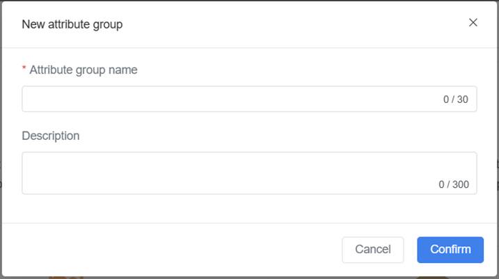
4. In the New public attribute groups window, enter the Attribute Group Name (required), and then click the Confirm button. The newly created attribute group will be displayed on the Digital Twins page.
Note: The attribute group name must start with Chinese, Japanese, English or numbers, and does not support special characters.
5. Click the details button ![]() of attribute group to open attribute group details page.
of attribute group to open attribute group details page.
6. Click the New button to add attributes for the attribute group.

7. In the New Attribute window, fill in the attribute information. For example, you can create an attribute for rotation angle:
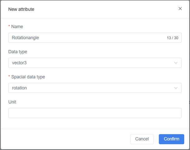
Name (required): must start with Chinese, Japanese, English or numbers, and not exceed 30 characters.
Data Type: please refer to Data types of attributes.
8. Click Confirm and the newly added attribute will be displayed in the attribute list of the Attribute group details page. You can click the delete button ![]() or edit button
or edit button ![]() to delete or edit the attributes as needed.
to delete or edit the attributes as needed.

9. You can repeat steps 6-8 to add multiple attributes to the attribute group.
By following the above steps, you can create a new public attribute group and add attributes to it. When creating a digital twin template, you can easily reference the public attribute group and use its attributes to describe the digital twin.
To delete a public attribute group, you can click the delete button ![]() for the attribute group and click Confirm in the prompt window to complete the deletion of the public attribute group.
for the attribute group and click Confirm in the prompt window to complete the deletion of the public attribute group.
To edit the name of a public attribute group, you can click the edit button ![]() for the attribute group on the attribute group details page, modify the Attribute group name in the Edit attribute group window, and then click Confirm to complete the editing of the attribute group name.
for the attribute group on the attribute group details page, modify the Attribute group name in the Edit attribute group window, and then click Confirm to complete the editing of the attribute group name.
Digital twin
A digital twin is an equivalent mapping of a physical entity in the digital world. Each digital twin is a specific instance of a digital twin template.
You can create, edit, delete, or view digital twins on the digital twins page.
Create a digital twin
Creating a digital twin means creating a digital twin based on a digital twin template, which can inherit metadata attributes, behavior trees, resources, sub-templates, and associated digital twins from the template.
Steps
1. Select the storage directory for the digital twin on the Digital Twin page.
2. Click the New button.
3. In the New digital twin window, select the digital twin section.

4. In the pop-up window, fill in the information for the digital twin.
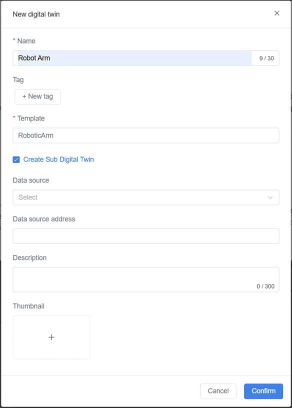
Name (required): The name of the digital twin.
Template (required): The digital twin template.
Create a Sub Digital Twin: When a template A contains a sub template B, if this configuration is selected when creating a digital twin using template A, the system will create two independent digital twins for template A and sub template B at the same time.
Data Source: The data source of the digital twin can be divided into three types: HTTP, HTTPS, and TCP.
Data Source Address: It can be a real data interface or a simulated data script.
- Real data interface: Fill in the IP address specified in the MQTT server access information.
- Simulated data script: The script needs to be uploaded to DataMesh FactVerse, and the storage path should be filled in the data source address. Format specification: SimulationFile:/storage path/filename.iotsim.
5. Click Confirm to complete the creation of the digital twin.
Behavior Tree
The behavior tree is a hierarchical node tree that controls the decision-making process of the digital twin, forming a series of decision logic to realize the operating mechanism of the digital twin. Note: you can create and edit the behavior tree in the FactVerse Designer and delete and move the behavior tree on FactVerse.
Scene
The Digital Twins page provides scene management functions that can be used in conjunction with FactVerse Designer.
The scene operation instructions are as follows:
- Create a new scene project: On the Digital Twins page, you can click the New button to create a new blank scene project. You can then open and edit the scene project using FactVerse Designer.
- Delete a scene project: Click the delete button
 corresponding to the scene project to delete it.
 - View scene project details: Click the detail button
 corresponding to the scene project to open the Scene Details page and view the scene project details.
Creating a new scene
Steps
1. On the Digital Twins page, select the storage directory for the scene and click the New button.

2. In the New digital twin window, select the Scene section.

3. In the New Scene window, fill in the information for the scene project.
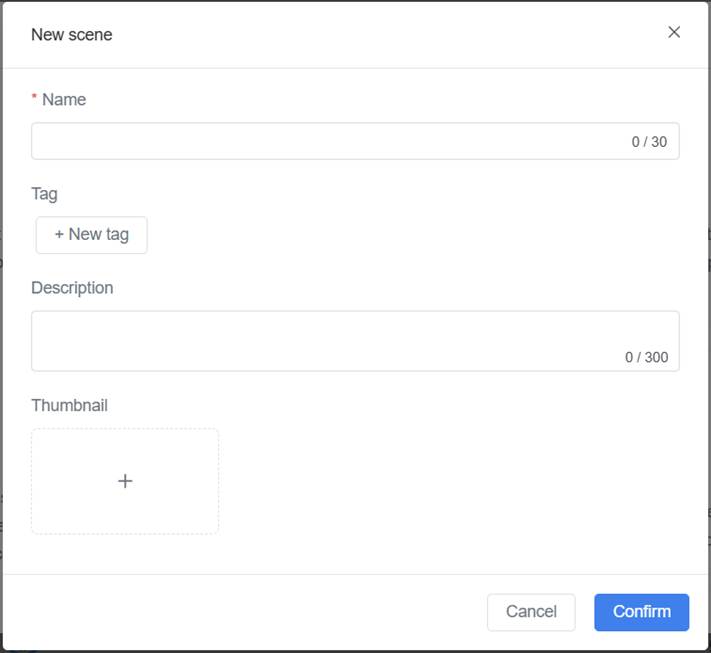
4. Click Confirm to complete the scene creation.
Viewing scene details
On the Digital Twins page, click the detail button ![]() corresponding to the scene you want to view to open the Scene Details page.
corresponding to the scene you want to view to open the Scene Details page.

The Scene Details page displays basic information about the scene, including the scene name, tags, creator, creation time, and description. The bottom of the page includes the functions corresponding to the Digital twin list, Position list, Behavior tree list, and Task List.
Reference and manage digital twins
On the scene detail page, you can reference, configure, and manage digital twins through the Digital twin list.

The Digital twin list displays the following information:
- Digital twin name: Shows the name of the digital twin. Click to view details.
- Visibility:
- Private: By default, newly created digital twins are set to private. They are only bound to the current scene and stored in a dedicated cloud location for that scene. These digital twins are not displayed in the resource directory, and only the creator can view and manage them within the scene. Other users cannot access them.
- Public: The creator can make the digital twin public, storing it in the cloud resource directory. Any user with access to the directory can view it.
- Workstation name: If the digital twin is bound to a workstation, the associated workstation name will be displayed.
Available operations:
|
Operation |
Description |
|
Reference digital twins |
Click the Reference button, select an unused public digital twin, and add it to the current scene. |
|
Delete reference |
Click the Delete icon |
|
Set workstation |
Click the Set Workstation icon ⚠️ Each digital twin can only be bound to one workstation. |
|
View digital twin details |
Click the twin name or Details icon |
Reference rules:
- Unique reference limitation: A digital twin can only be referenced by one scene and cannot be reused in multiple scenes.
- Remove references:
- Once a digital twin is removed from a scene, it will reappear in the digital twin library and can be referenced again.
- If the scene containing the digital twin is deleted from the cloud, the system will automatically remove its reference, allowing the digital twin to be referenced once more.
BIM Data
The BIM Data service mainly supports the use of DataMesh Inspector. Through BIM Data service, users can create, manage, and browse BIM scene projects, and view and manipulate them in DataMesh Inspector.
To access BIM data, select Digital Assets in the function module navigation bar, then click on BIM Data, and you will enter the BIM Data page. This page shows a list of all BIM scene projects created and publicly displayed under the current directory. You can create new projects, delete and search for building scenes, and view detailed information about them.

Create new BIM scenes
Create new BIM scenes:
1. Log into the DataMesh FactVerse platform. In the function module navigation bar, select Digital Assets > BIM Data to enter the BIM Data page.
2. On the BIM Data page, click the New button to open the New window.

In the New window, you need to fill in the following information about the BIM scene:
- Name (required): The name of the BIM scene.
- Directory (required): The storage directory for BIM scenes. After you create a BIM scene, the system will create a hidden folder named after the scene within this directory to store the built files and the digital twins of the devices. For example, after the BIM scene “DM Office” is successfully created, a hidden folder named “DM Office” will be automatically created in its directory.
- Description: You can add some text to describe or characterize the BIM scene.
- Cover: You can select a standard format image from your local device as the cover of the scene. Choosing the right cover image can enhance the recognizability of the BIM scene.
3. After filling in the BIM scene information, click the Confirm button.
Import scene resources
Scene resources are the model assets that make up a scene. These resources are packaged in a .zip file, generated from processed Revit files, and include the following:
- Component FBX files
- Excel file containing component positioning, rotation information, and BIM data
Note: Before importing scene resources, ensure that the target BIM scene has been created.
Steps
1. Convert model files: Use local tools to convert Revit files to the required format, or email bimfile@datamesh.com to request the BIM model conversion service from DataMesh. Before making the request, review and confirm the relevant Service Level Agreement (SLA).
2. Upload resource package: Upload the generated .zip file to the resource library.
3. Import resources into the BIM scene
a) In the BIM scene details page, click the Import button to open the Select resource window.

b) In the Select resource window, choose the required resource (the .zip file generated after conversion), then click the Confirm button to import the resource to the BIM scene.

4. Check import status: After the file is imported, its status will be “Import successful, waiting for building.”
Through the above method, you can successfully import scene resources into the specified BIM scene.
Scene building
Scene building combines the converted .zip files of BIM models from different disciplines into a complete BIM scene, supporting facility management and engineering inspection requirements.
Steps for scene building
1. On the BIM scene details page, select the files to be built (files with the status “Import successful, waiting for building”).
2. Click the Build button and confirm the consumption count in the popup prompt. Note: In this version, you don’t need to worry about the consumption count and can confirm the processing directly.

3. Files being built will be unavailable for selection and will show as “Building.” You can manually refresh the page based on the “Estimated Build Completion Time” to check the status.
4. When the file status shows “Build successful,” the file has been successfully built. At this point, you can proceed with subsequent operations, such as importing other building models for incremental building. Once the scene construction is complete, you can use DataMesh Inspector to open the BIM scene for business execution.
If the scene building fails, please contact support@datamesh.com for technical assistance.
Manage equipment digital twins
Create equipment digital twins
Create equipment digital twins within the BIM scene.
1. Create digital twin template: Use the FactVerse platform or FactVerse Designer to create a digital twin template for the target equipment based on actual business needs. If using preset templates from the Virtual Factory DLC, this step can be skipped.
2. Export Template: Export the Excel template from the BIM scene, which includes sample data.

3. Fill in the Excel template: Refer to the equipment relationships in your equipment management system (such as Building Management System) to fill in the following information in the template:
- Digital Twin information:
- Digital Twin (Required): The name of the digital twin to be created. The created digital twin will be automatically saved in the hidden folder of the BIM scene.
- Floor: The floor where the equipment is located.
- System Ownership: The system to which the equipment belongs.
- Equipment Relationships: After adding relationships, you can view the relationships between equipment in the DataMesh Inspector in conjunction with the real environment.
- Target digital twin: The digital twin of the equipment that has a relationship with this equipment.
- Relationship Description: A description of the logic relationship for digital twins.
- Relationship Type: Relationship types defined based on Brick Schema, with 4 options provided by the system:
- feeds: Indicates that one device provides services, resources, or data to another device or system. For example, a chiller provides cooling water to an air handling unit.
- hasPart: Indicates that a device is part of another device or system. For example, an air handling unit may include components like fans and filters.
- hasPoint: Indicates the relationship between a device and its measurement or control points. For example, an HVAC system may have multiple temperature sensors to monitor temperatures in different areas.
- hasLocation: Indicates the relationship between a device and its location. For example, a temperature sensor is installed in a specific room to monitor the temperature of that room.
- Information Required for Creating Digital Twins:
- Digital Twin Template (Required): The name of the digital twin template used for the equipment, such as a generic cabinet template.
- Digital Twin Template External ID: If a template with the same name exists in the current tenant’s digital asset catalog, use the External ID to help the system accurately locate the template when creating the digital twin.
- BIM Component Information: Information about the BIM components that match the digital twin of the equipment.
- BIM Component Attribute Name (Required): An attribute from the BIM component, such as Element ID or Name, used to bind the digital twin created from this row of information.
- BIM Component Attribute Value (Required): The attribute value of the BIM component used to bind the digital twin created from this row of information.
Notes:
- The two rows highlighted in yellow in the template are example data. To avoid accidental edits, these cells are locked for protection; please start filling in from row 5.
- Ensure all required information is correctly filled out and check that the format of the template complies with system requirements before importing.
4. Import Excel template: On the BIM Scene Details page, import the completed Excel template.
The system will generate digital twins for each piece of equipment based on the imported information and associate them with BIM components in the scene. The generated digital twins will appear in the digital twin list in the Equipment relationship panel, and the relationships can be displayed in both relationship diagram and table formats.

View relationships between digital twins
You can view the relationships between equipment digital twins to understand their relationships in practical scenarios. Follow these steps to view the relationships between digital twins:
1. Access the BIM Scene Details page.
2. Click the Equipment Relationship tab.
3. View relationship:
- Relationship Diagram: Click the “Relationship Diagram” icon
 , and the system will display the connections between the selected digital twin and other digital twins in a graphical format. Through the graphical interface, you can intuitively understand the upstream and downstream relationships, control relationships, etc., between the equipment.

- Relationship Table: Click the “Relationship Table” icon
 , and the system will list detailed information about all relevant digital twins in a tabular format, including relationship types, target digital twins, relationship descriptions, etc.

Edit equipment relationships
You can edit the relationships between equipment digital twins to ensure they reflect the actual business logic. The following steps will guide you through editing these relationships:
1. Access the BIM Scene Details page.
2. Click the Equipment Relationship tab.
3. Click the “Relationship Table” icon ![]() to open the relationship table for the digital twins.
to open the relationship table for the digital twins.
4. Edit equipment relationships:
- Add relationship:
a) On the equipment relationship list page for the BIM scene, click the New button to open the creation window.
b) Select the Target digital twins and Relationship type.
c) (Optional) Enter a description of the relationship.
d) Click Confirm to save the new relationship.
- Modify relationship:
a) Locate the relationship entry you want to modify in the relationship table.
b) Click the edit button ![]() to open the Edit window
to open the Edit window
c) Update the target digital twin, relationship type, or relationship description.
d) Click Confirm to save the changes.
- Delete relationship:
a) Find the relationship entry you want to delete in the relationship table.
b) Click the delete button ![]() , and the system will prompt you to confirm the deletion.
, and the system will prompt you to confirm the deletion.
c) Upon confirmation, the relationship will be removed from the list, and the association will no longer be valid.
Edit equipment digital twins
You can edit the basic information of an equipment digital twin to ensure it accurately reflects the actual equipment information. Follow these steps to edit an equipment digital twin:
1. Access the BIM Scene Details page.
2. Click the Equipment Relationship tab.
3. Click on the detail icon ![]() of the digital twin to open the Digital Twin Details page.
of the digital twin to open the Digital Twin Details page.

4. Click the edit button ![]() to modify the name, data source, identifier, or description.
to modify the name, data source, identifier, or description.
5. After making the changes, click Confirm.
