How Can We Help?
Application Examples
Example 1: Simulation Playback Based on Historical or Simulated Data Sources
Scenario Overview
A production line device has accumulated operational data. The user wants to replay it in DFS to verify equipment–line coordination or, when no real data is available, use simulated data to drive the same process for testing purposes.
This example demonstrates how to use a simulated data source to drive a robotic arm’s motion.
Step 1. Build the Digital Twin Scene
- Prepare the Model
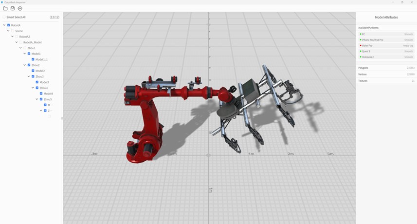
a) Open the model in DataMesh Importer.
b) Select nodes in the model hierarchy according to the motion requirements for data-driven control.
c) Upload the model to your FactVerse resource library.
- Create and Configure the Template
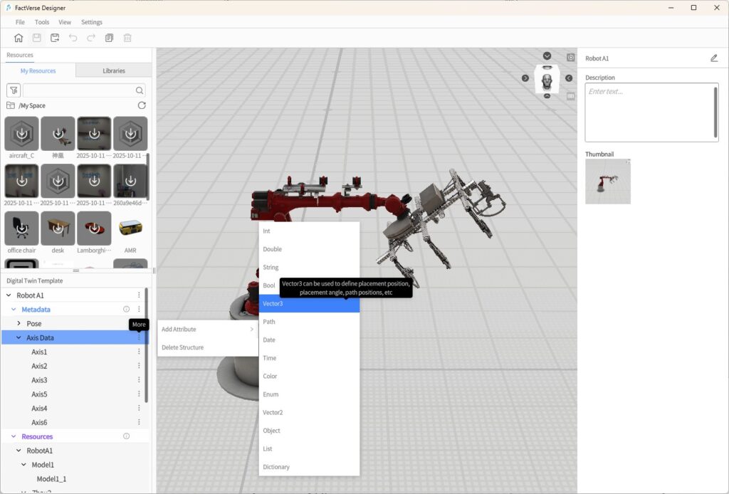
a) In FactVerse Designer, create a new template.
b) Place the robotic arm model and add structures for “Joint Rotation Angles” with rotation attributes (vector3).
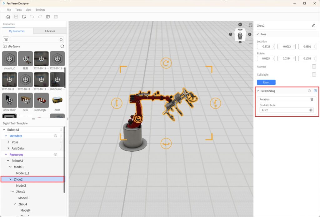
c) In the Data Binding section, associate model hierarchy nodes with the corresponding joint rotation attributes, then save the template.
- Build the Digital Twin Scene
a) Create a new digital twin scene, generating a digital twin “RobotA1_1” from the existing robotic arm template.
b) Adjust the digital twin’s position and layout, complete the scene setup, and save it.
Step 2. Create a Simulation Task
- Import the Digital Twin Scene
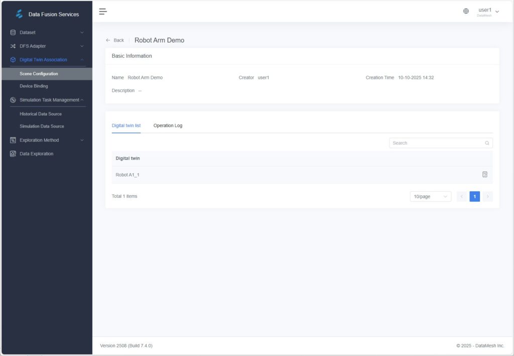
In DFS, go to [Digital Twin Association] > [Scene Configuration], click [Import], and select the scene to import.
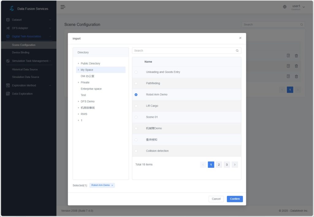
After import, the digital twin list is available on the scene details page.
- Import Device Information
You can import device information using either of the following methods:
- Configure an adapter instance on the [Adapter Instances] page and send device data. The system will automatically generate the corresponding device information.
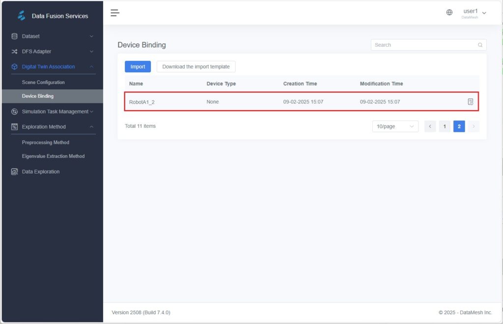
- Alternatively, go to [Digital Twin Association] > [Device Binding], click [Import], and upload a simulated data file to import device information manually.
Once successfully imported, the device information will appear in the device list.
For example, “RobotA1_2” is a device name that will be required in subsequent simulation tasks.
- Create a Simulated Data Source Task
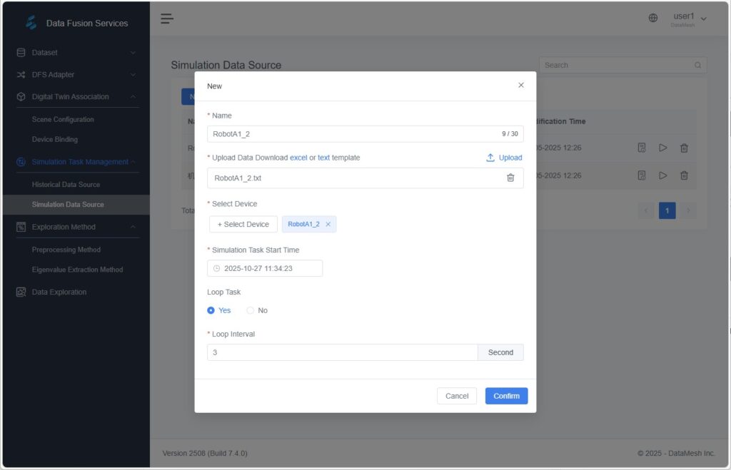
a) Go to [Simulation Task Management] > [Simulation Data Source], create a new task, and upload your data file.
b) Bind the data to the corresponding device and set a playback interval time.
Example Data File (example.xlsx)
Device Name (name) | Device Attribute (key) | Attribute Value (value) | Timestamp |
RobotA1_2 | A1Pos | 270,72.68018,0 | |
RobotA1_2 | A2Pos | 356.0886,330.6853,6.112504 | |
RobotA1_2 | A3Pos | 358.6275,297.3004,359.3982 | |
RobotA1_2 | A4Pos | 0.8182315,352.0203,268.8459 | |
RobotA1_2 | A5Pos | 73.55777,344.6217,255.9178 | |
RobotA1_2 | A6Pos | 8.447219,89.98469,1.294706E-06 |
- Bind Data to the digital Twin
a) Go to [Digital Twin Association] > [Device Binding], select the target device, and open its details page.
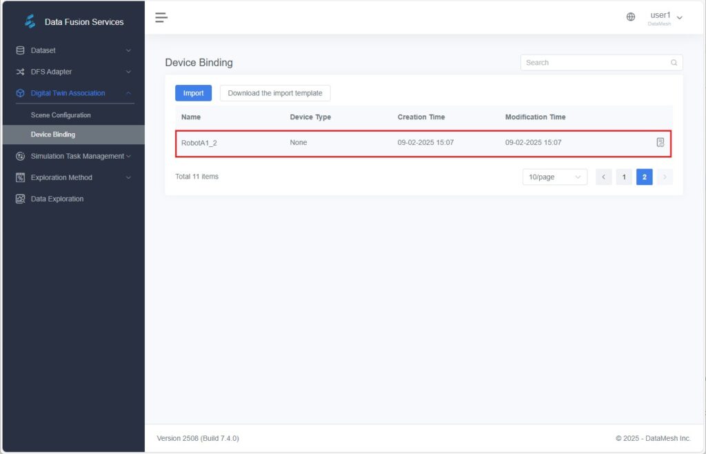
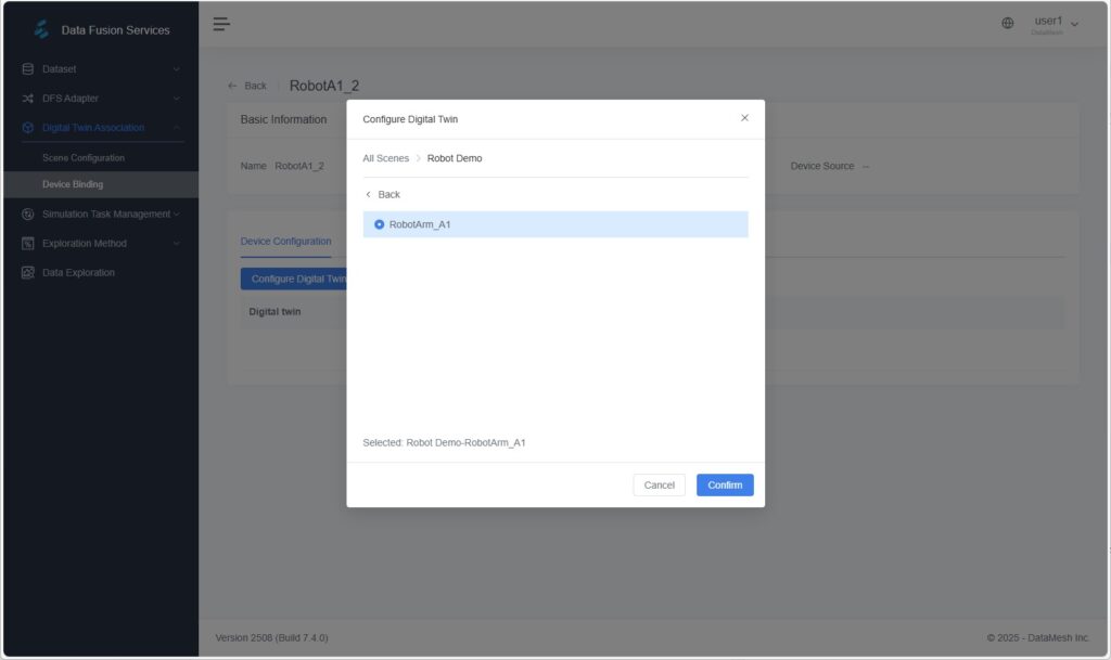
b) In the device configuration panel, click [Configure Digital Twin] and select the corresponding digital twin in the pop-up window.
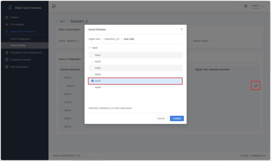
c) In the attributes section, click the Bind icon ![]() to map each device attribute to the corresponding twin attribute.
to map each device attribute to the corresponding twin attribute.
Step 3. Scene Verification
- Return to FactVerse Designer, open the bound digital twin scene.
- Click [Debug Playback] and observe the robotic arm joints moving according to the simulated data.
Example 2: Designer Simulation Record Analysis
Scenario Overview
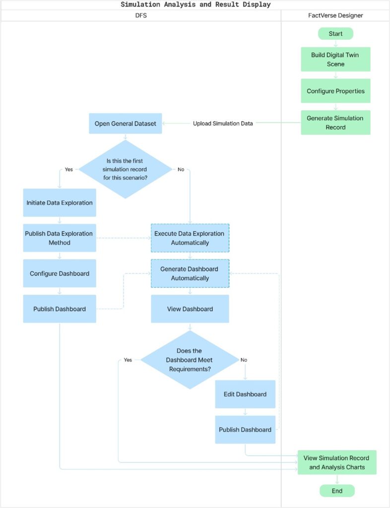
Multiple simulations are run in Designer to compare production efficiency under different configurations. Results are automatically analyzed and visualized in a dashboard for decision-making.
Step 1. Preparation
- Build the Scene:
In FactVerse Designer, construct a digital twin scene and configure the parameters to be tested. - Generate Simulation Records:
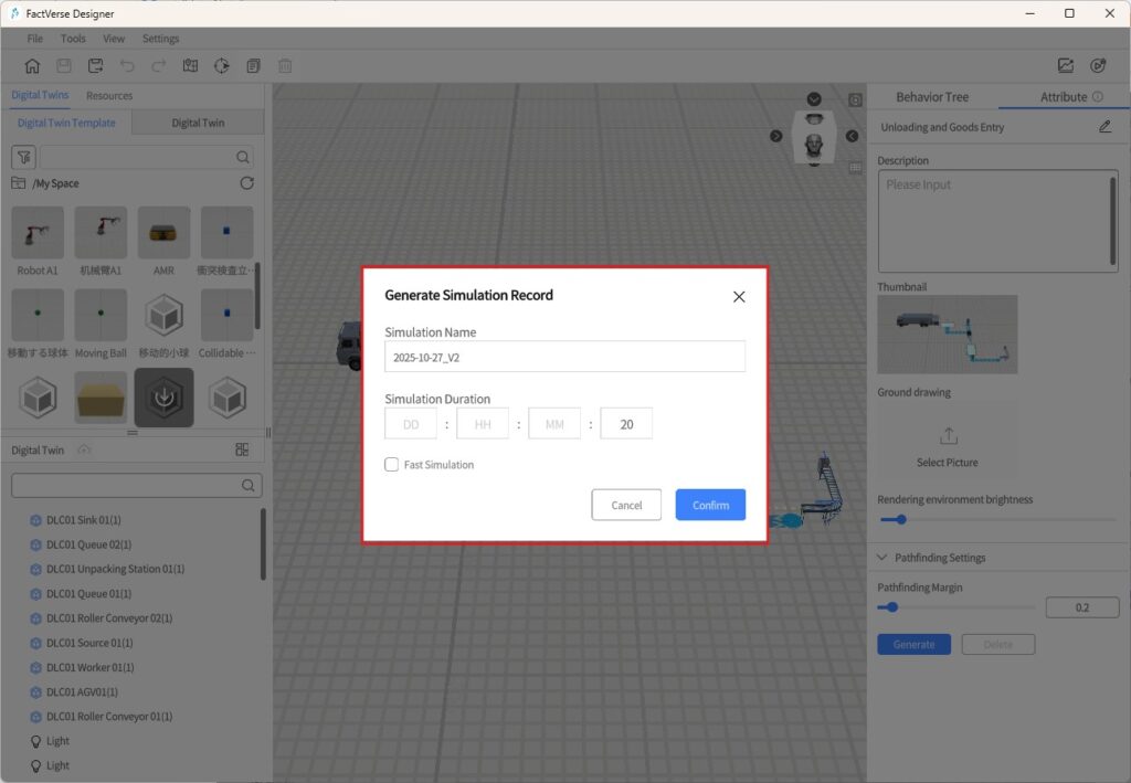
- Run the scene under different configurations or durations to produce multiple simulation outcomes.
- The system generates corresponding simulation playback records, which serve as data sources for later analysis.
- Upload to DFS:
- After the simulation completes, the records are automatically uploaded to DFS.
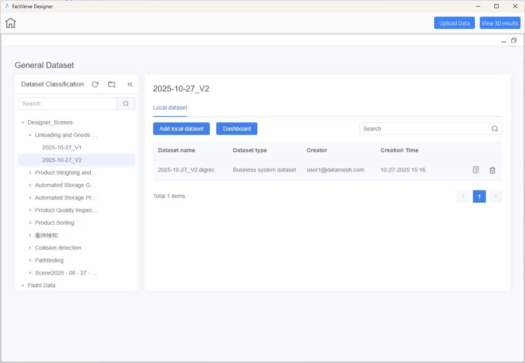
- Once uploaded, you can open the [General Dataset] page in Designer to perform data analysis.
Step 2. Data Exploration and Publishing
The goal of this step is to:
- Convert simulation playback records into analytical result datasets.
- Provide data inputs for dashboard visualization.
- Start Data Exploration
- In the dataset classification panel, select the dataset uploaded from Designer.
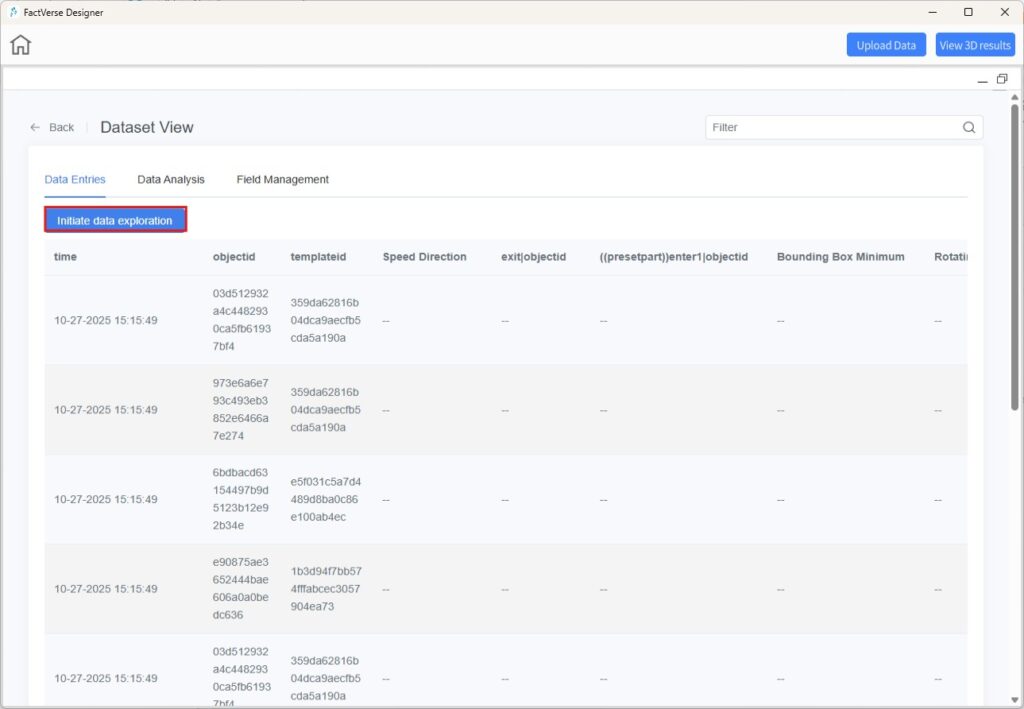
- Open the dataset view page, go to the Data Entries tab, and click [Initiate Data Exploration].
- Publish the Exploration Method
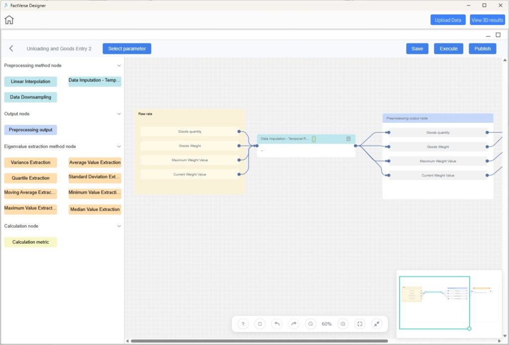
- Execute and publish the exploration workflow.
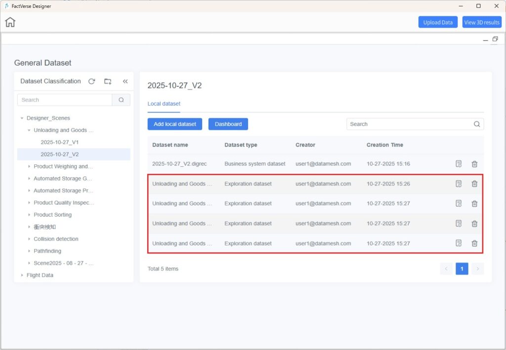
- The execution results are output as a new Exploration Dataset.
- Each time a new simulation record is generated, DFS automatically runs the corresponding exploration task.
Step 3. Result Reuse and Analysis
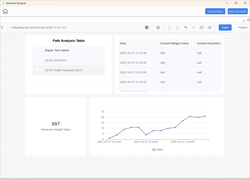
- Configure Dashboard
- Create and save a dashboard to visualize exploration results.
- Publish Dashboard
- Once published, DFS automatically updates the exploration results and refreshes the dashboard each time a new simulation record is generated.
- View and Analyze
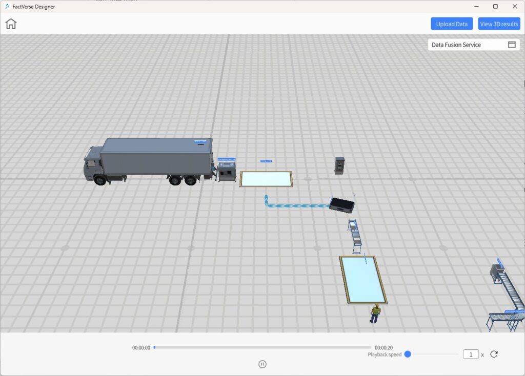
- Use [View 3D Results] to replay the simulation process, evaluate path efficiency and rationality, identify optimization opportunities, and plan better scheduling strategies.
- Adjust parameters based on insights, rerun the simulation, and review the updated dashboard results.
Example 3: Real-Time Robotic Arm Data Driving a Digital Twin
Scenario Overview
In real-world production, robotic arms need to synchronize with sensors and control systems in real time.
This example demonstrates how to use DFS to connect and stream live robotic arm data, drive its digital twin in real time, and trigger alerts when thresholds are exceeded.
Step 1. Preparation
- Create an Adapter Instance
- In DFS, navigate to [Adapter Instance].
- Click [New], and fill in the IP address and port number for the robotic arm data acquisition instance.
- Configure Node-RED Workflow
- Click the Edit icon
 to open the Node-RED Editor.
 - Define data acquisition and preprocessing logic: receive real-time data (joint angles, end-effector positions, etc.) from the robotic arm controller, convert it to standardized JSON format, and forward it to DFS internal data channels.
- Deploy the flow.
Step 2. Bind Device and Digital Twin
- Device Binding
- Go to [Digital Twin Association] > [Device Binding], select the connected robotic arm device.
- Open its details page and click [Configure Digital Twin].
- Attribute Mapping
- Map device attributes (e.g., A1Pos, A2Pos, A3Pos …) to the corresponding joint rotation attributes of the twin template.
- After saving, the real-time joint angles of the robotic arm are synchronized with the digital twin.
Step 3. Scene Verification
- Return to FactVerse Designer, open the bound scene.
- Click [Debug Playback] to observe the robotic arm’s joints moving in real time according to live data.