How Can We Help?
Functions
Create Digital Twin Template
In FactVerse Designer, you can create digital twin templates in two ways to meet different needs:
Customize Preset Templates
The Virtual Factory DLC provides several common preset templates, such as generators, conveyors, and AGVs. Users can select these preset templates and modify them as needed. This makes creating digital twin templates simple and efficient.
Example: Customized Queue Template
In this example, we will use the Queue template from the Virtual Factory DLC, create a customized Queue template, and modify its default attribute values.
Steps
- Click the Open Template button on the homepage.
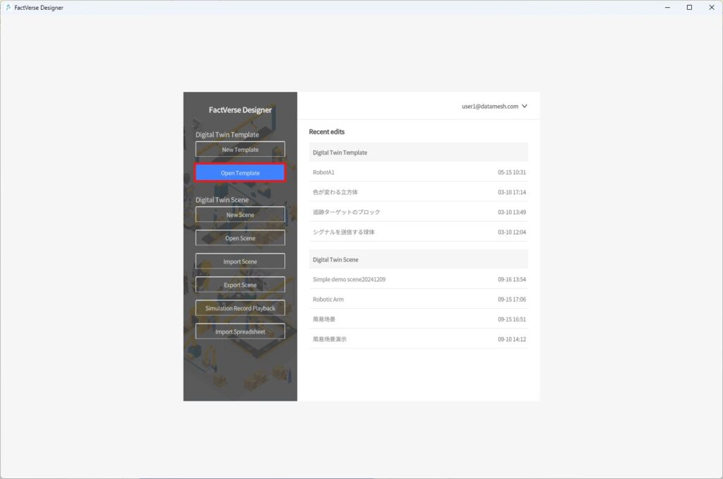
- In the prompt window, choose the “Queue” template and click the Open

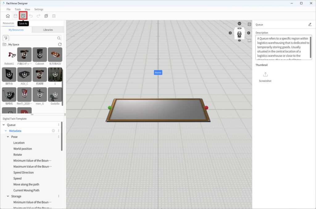
- Click the Save As button to open the Save window.
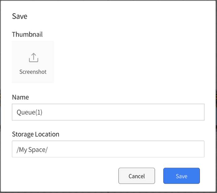
- In the Save window, choose the storage directory, specify the template name, and then click Save to complete the template’s save as process.
- In the Digital Twin Template pane, select the Width of Goods under the Storage In the Attribute Pane on the right side, change the default value to 0.2.
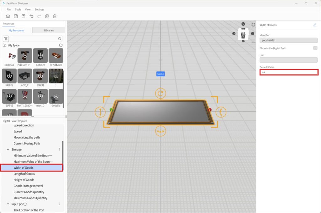
- Similarly, change the default values for “Goods Length” and “Goods Height” to 0.2.
Create a New Template
You can create a fully customized digital twin template from scratch to meet the requirements of specific scenarios.
Example: A Color-Changing Cube
In this example, we will create a “Color-Changing Cube” that automatically changes its color when it receives different signal values.
Objective
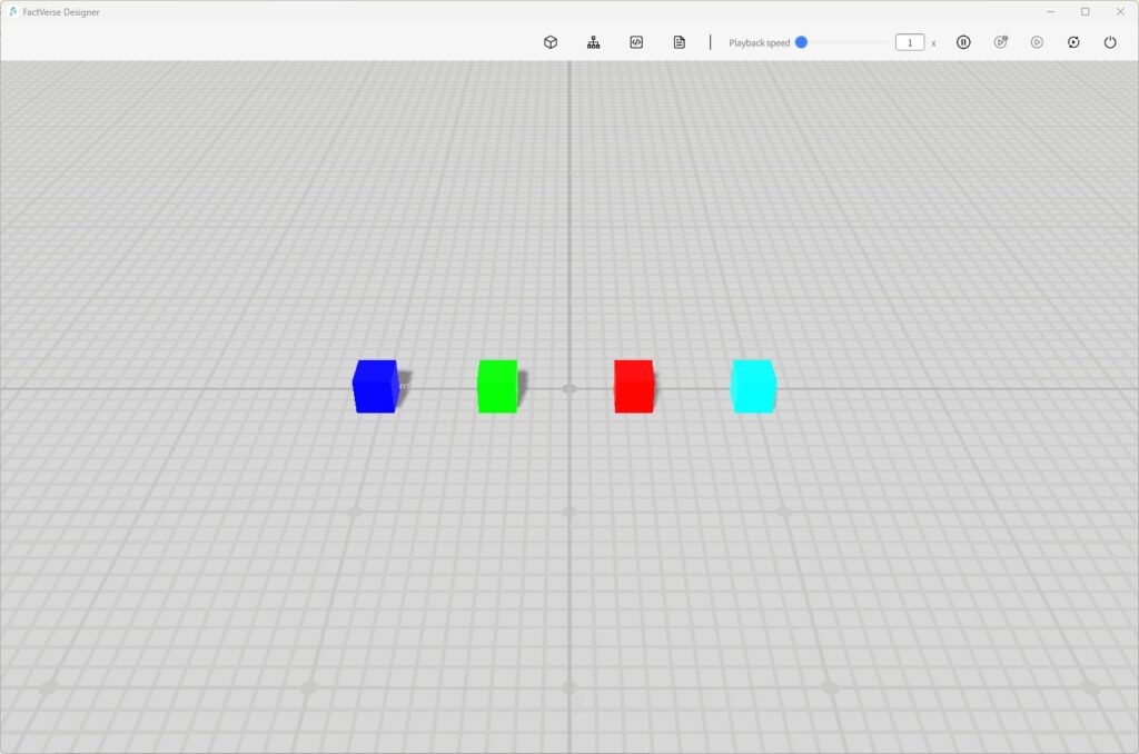
Logic implementation: When the Signal attribute value is 1–4, the cube changes its color to blue, green, red, or cyan, respectively.
- Create a Cube Template
a) On the Home Page, click New Template to open the Template Editor.
b) In the Libraries, click Cube to enter placement mode, then click in the scene area to place a cube.
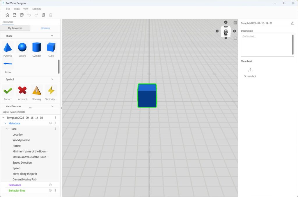
c) After placement, right-click to exit placement mode.
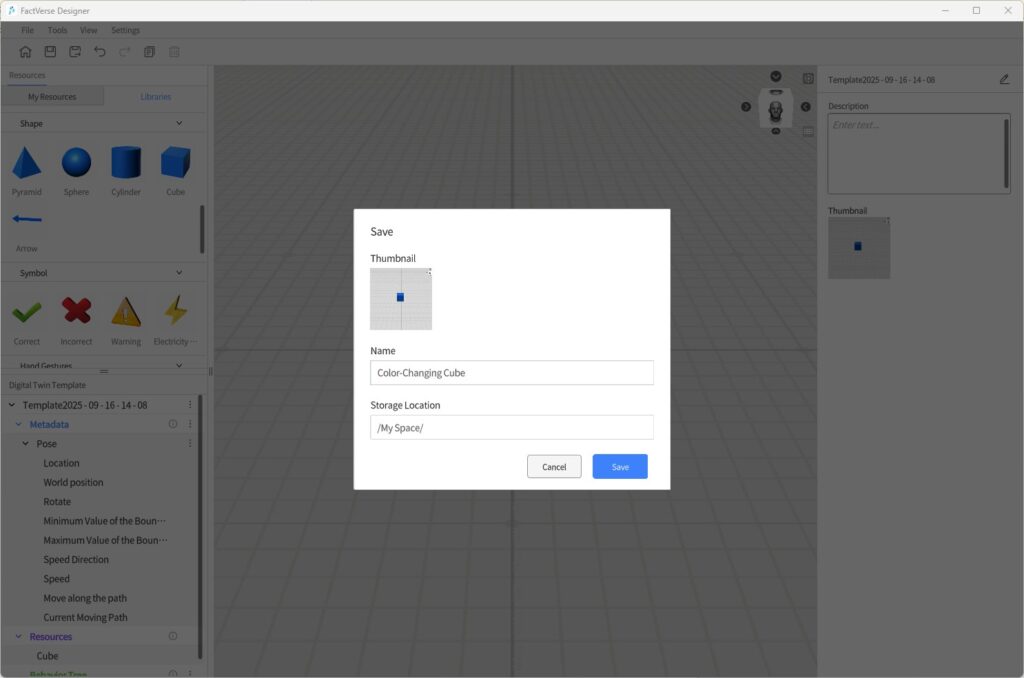
d) In the toolbar, click the Save button![]() and save the template with the name Color-Changing Cube.
and save the template with the name Color-Changing Cube.
- Add the Main Function Structure
a) In the Digital Twin Template Pane, click ︙ next to Metadata and select Add Structure.
b) Scroll down to locate the new structure Part_1. Click Part_1 and in the Attribute Panel rename it to Main Function.
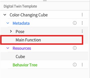
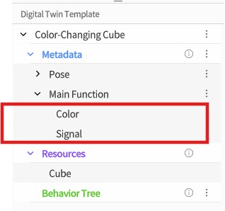
c) Under the Main Function structure, add two attributes: Color (type: Color) and Signal (type: Int).
- Bind Data to the Color Attribute
a) In the scene area, select the cube model.
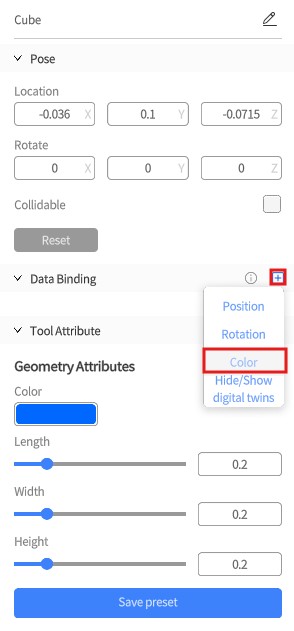
b) In the Attribute Panel on the right, next to Data Binding, click Add![]() and select the Color
and select the Color
c) In the binding window for the Color attribute, click the selection button ![]() and choose the Color attribute under the Main Function
and choose the Color attribute under the Main Function
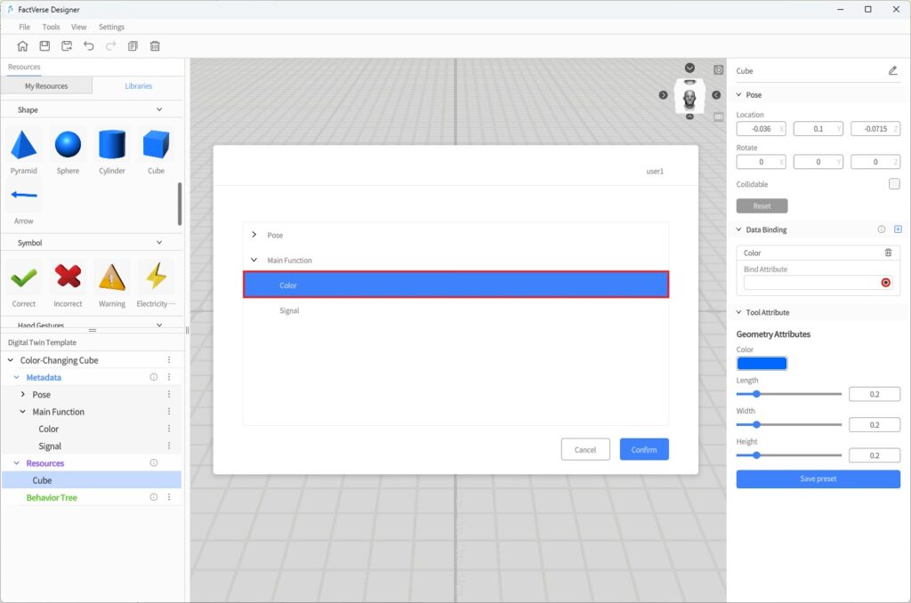
d) Click Confirm to complete the binding.
This step ensures that the digital twin’s “Color” attribute can drive changes to the model’s color.
- Create a Behavior Tree
a) In the Digital Twin Template Pane, click ︙ next to Behavior Tree and select Create Behavior Tree.
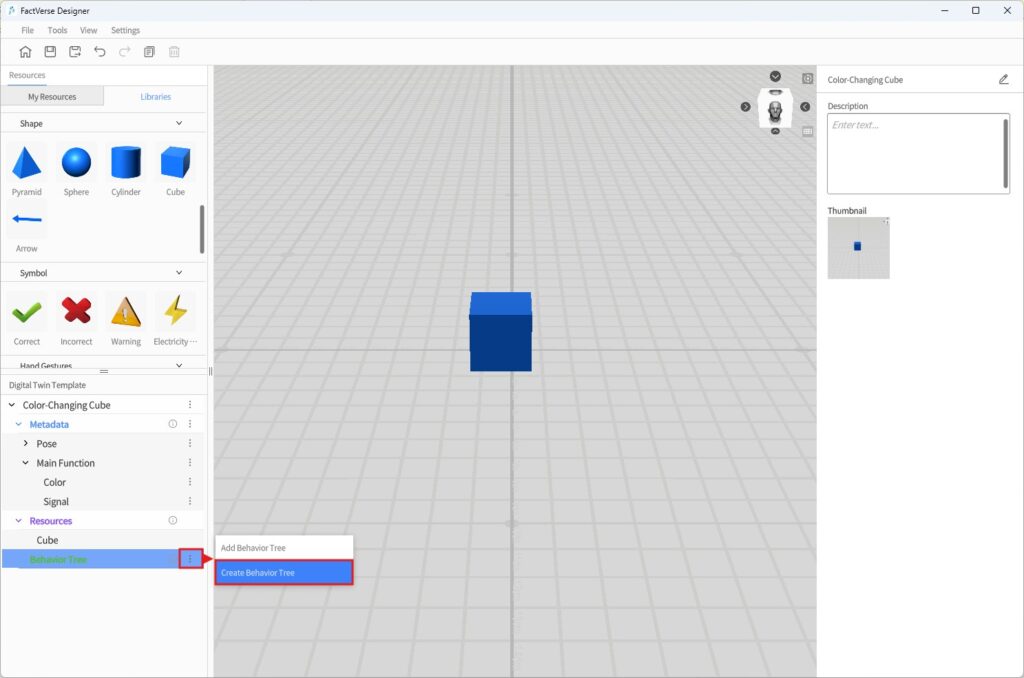
b) Save the behavior tree and name it Signal-to-Color Listener.
- Edit Behavior Tree Logic
a) Double-click Signal-to-Color Listener to open it in the Behavior Tree Editor.
b) Under the root node, add a Selector
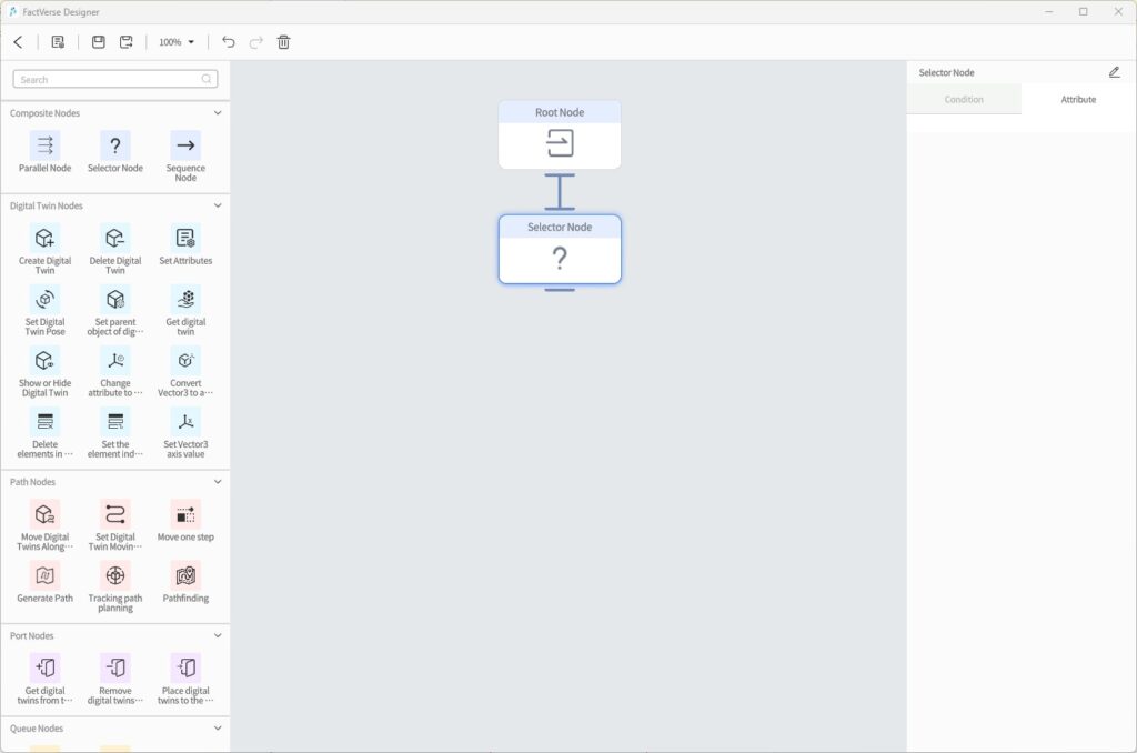
c) Under the Selector node, add 4 Sequence Nodes. For each, configure a condition using Compare Two Attribute Values.
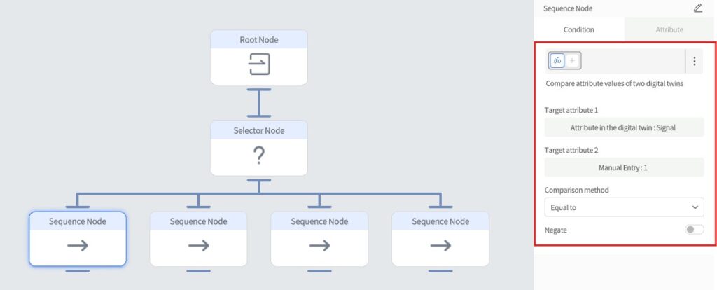
Condition Configuration (Compare Two Attribute Values)
| Sequence Node | Attribute 1 | Signal Value (Attribute 2) | Comparison |
| Sequence 1 | Signal | 1 | Equal to |
| Sequence 2 | Signal | 2 | Equal to |
| Sequence 3 | Signal | 3 | Equal to |
| Sequence 4 | Signal | 4 | Equal to |
Each sequence node defines a “If Signal = X, then set Color = Y” logic.
d) Under each Sequence Node, add a Set Attributes node to change the cube’s color.
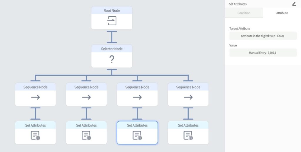
Set Attribute Node Configuration
| Node | Attribute | Value (RGBA) | Color |
| Set 1 | Color | 0,0,1,1 | Blue |
| Set 2 | Color | 0,1,0,1 | Green |
| Set 3 | Color | 1,0,0,1 | Red |
| Set 4 | Color | 0,1,1,1 | Cyan |
- Save the Behavior Tree
a) In the toolbar, click the Save button to save the behavior tree.
b) Click < Exit to leave the Behavior Tree Editor.
- Save the Template
Click the Save button in the toolbar to save the template.
- Exit the Template Editor
Click the Home button to exit the Template Editor. The custom template is now complete.
By following these steps, you can create a digital twin template for a cube that changes color based on its Signal attribute. Create a cube instance using this template, set different signal values, and observe the cube change color accordingly.
Digital Twin Management
Create Digital Twins
FactVerse Designer provides three methods for creating and managing digital twins, supporting flexible construction, batch creation, or full-scene imports to meet different needs.
| Creation Method | Suitable Scenarios |
| Manual Creation | Quickly add a small number of digital twins or make local adjustments |
| Template Excel Import | Batch add/modify multiple twins under a single template |
| Scene Excel Import | Restore an entire scene structure in one step; useful for migration or global management |
Manually Create a Digital Twin
Steps
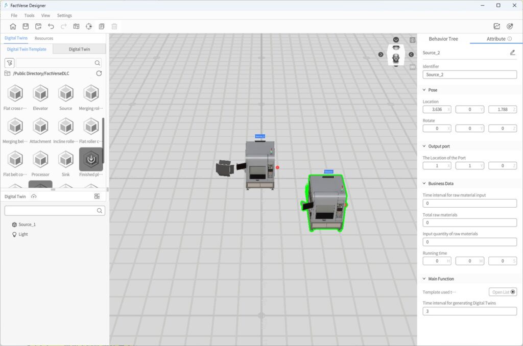
- In Digital Twins Library > Digital Twin Template, click the target template to enter Placement Mode.
- Once the template is loaded, a preview model with a green outline will appear.
- Left-click in the scene area to confirm the placement location.
- After placement, a new digital twin is automatically created and named according to the rule: TemplateName_Index.
Import Digital Twins via Template Excel Spreadsheet
This method is suitable for batch creation or maintenance of multiple digital twins under the same template.
Function Overview:
- You can choose to export an empty template structure or a template file containing instance data.
- Supports adding, modifying, and deleting digital twins directly in the Excel spreadsheet.
- Supports full editing of configuration items such as attributes and positions.
- After importing the spreadsheet, the platform will automatically generate or update all related twins.
Steps
1. Open a Twin Template
On the Home Page, click the Open Template button to select and open the digital twin template that you want to use for batch creation.
2. Export Spreadsheet
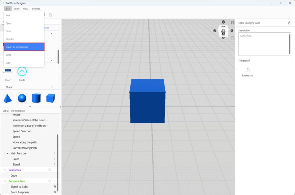
a) In the Template Editor menu bar, click File > Export as Spreadsheet.
b) In the pop-up window, choose the export content:
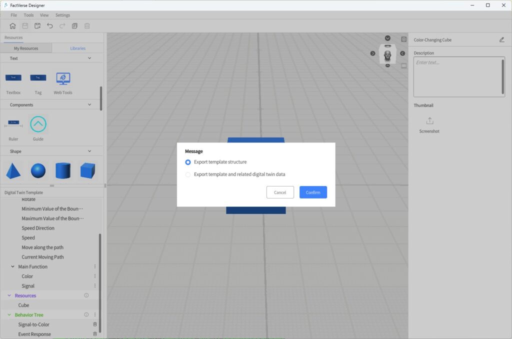
- Export template structure (default): Exports a lightweight spreadsheet with only template field definitions, without any instance data.
- Export Template and related digital twin data: Exports a complete spreadsheet containing both the template structure and all associated twin instance data. This file can be used for batch modification or addition of twin data.
c) Click Confirm to save the Excel file locally.
3. Edit the Excel Spreadsheet
In the exported Excel file, you can edit or add digital twin data.
- Each row represents one digital twin.
- Digital Twin ID:
- If you enter the ID of an existing digital twin, the system will update that twin’s data.
- If left blank, a new digital twin will be created upon import.
Field Structure Reference
| Field | Data Type | Format | Example |
| Digital Twin ID | String | Unique identifier of the digital twin | 12345-abcde |
| Digital Twin Name | String | User-defined name | Red Cube 1 |
| Identifier | String | Custom code | abcde-67890 |
| Storage Path | String | Path where the digital twin is stored | /My Space |
| Parent Object ID | String | ID of the parent digital twin (if any) | 12345 |
| Pose Location | vector3 | 3D coordinates of the digital twin in the scene | 1.0, 2.5, 0.0 |
Notes:
- To update an existing digital twin, the ID field must be filled.
- To create a new digital twin, leave the Digital Twin ID field blank.
- Before importing, make sure to close the Excel file after editing.
- For more details, see FactVerse Platform User Manual – Attribute Data Types.
4. Import Spreadsheet
a) Click the Home button ![]() to return to the Home Page.
to return to the Home Page.
b) On the Home Page, click the Import Spreadsheet button.
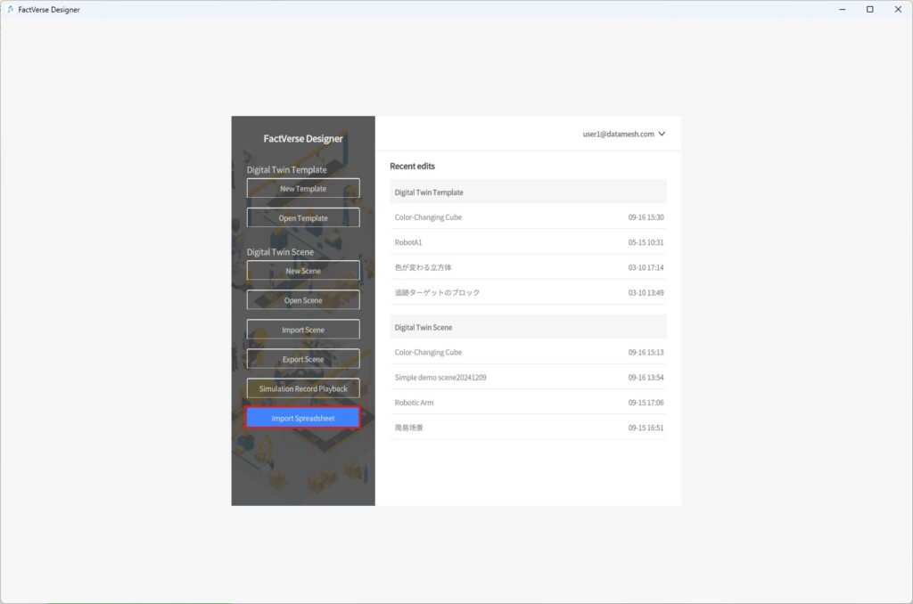
c) Upload the edited Excel file. The system will automatically create or update all related digital twins.
Import Digital Twins via Scene Excel Spreadsheet
This method is suitable for exporting or importing an entire scene structure, including multiple templates and all associated digital twins.
Function Overview:
- Supports centralized editing of digital twins across multiple templates.
- Allows quick restoration of the entire scene structure.
- Useful for project migration and batch configuration of attributes.
Spreadsheet Structure
| Worksheet Tab | Description |
| Rules | Instructions and formatting requirements |
| Scene_[SceneName] | List of template information used in the current scene |
| Template_[TemplateName] | Configuration of all twins under the template (one sheet per template) |
Note: For local digital twins, the Storage Path field will be empty.
Steps
- Open the target scene.
- Export the scene to an Excel spreadsheet: In the menu bar, click File > Export as Spreadsheet.
- Edit the spreadsheet: Add or modify attributes and positions of twins under any template. After editing, save and close the spreadsheet.
- Import the Excel spreadsheet: On the Home Page, click Import Spreadsheet. The system will automatically create or update the scene structure and all associated twins.
Mark as Cloud Digital Twin
By default, newly created digital twins are local digital twins, existing only within the current scene and stored in a hidden path on the platform. Other users cannot view or reuse them.
To enable resource sharing and cross-scene reuse, you can mark digital twins as Cloud Digital Twins and upload them to the cloud directory. If a digital twin is not referenced by any scene, users with access permissions can view and use it from the digital twin list.
Steps
1. In the scene, select one or more twins.
2. Click the Mark as Cloud Digital Twin button![]() .
.
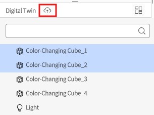
3. In the pop-up window, select the desired option:
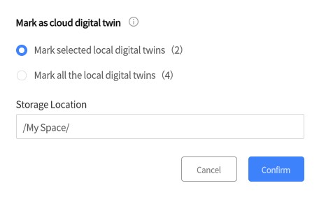
| Option | Description |
| Mark selected local digital twins (X) | Upload only the selected local digital twins. If the selection includes non- local digital twins or other resources, the system filters them out. X indicates the number of selected local digital twins. |
| Mark all local digital twins (X) | Upload all local digital twins in the current scene. X indicates the total number of local digital twins in the scene. |
4. Click Confirm:
- The icons of the marked digital twins change from gray to blue
 .
. - The digital twins are in a pre-marked state and are not uploaded until the scene is saved.
5. Save Scene:
- All pre-marked twins are uploaded to the cloud directory.
- After upload, users with permission can view and use them from the cloud directory.
Undo Instructions:
- Before saving the scene, you can cancel the pre-marked state.
- Even after saving, you can undo the public state with Undo, but you must save the scene again for changes to take effect.
Delete Digital Twins
In FactVerse Designer, the result of deleting a twin depends on whether it is a private twin (only exists in the current scene) or a cloud digital twin (uploaded to the cloud).
Steps
- Perform Delete:
- Select the target digital twin, then press the Delete key or choose Delete from the right-click menu.
- If deleted by mistake, click the Undo button in the toolbar to restore it.
- Deletion Result:
| Digital Twin Type | Result |
| Local Digital Twin | Permanently deleted, including attributes and behavior logic. Effective immediately. |
| Cloud Digital Twin | Only the scene reference is removed. The twin instance remains in the cloud resource directory. |
- Save the scene to make the deletion effective.
💡 Note:
- A twin can only be referenced by one scene. Deleting the reference removes its binding.
- Deleting a cloud digital twin from a scene does not delete it from the cloud. To completely delete a cloud digital twin from the platform, ensure that it is not referenced by any scene.
Rename Digital Twins
In FactVerse Designer, you can name or rename digital twins in a scene.
Note: Preset digital twins from FactVerse DLCs cannot be renamed.
Steps
1. Select the target digital twin in the scene.
2. In the Attribute Panel, click the Edit icon next to the digital twin name.
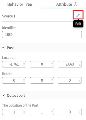
3. Enter a new name, then press Enter or click a blank area in the scene to confirm.
4. Click the Save button in the toolbar to save the scene and apply the change.
Custom Tools
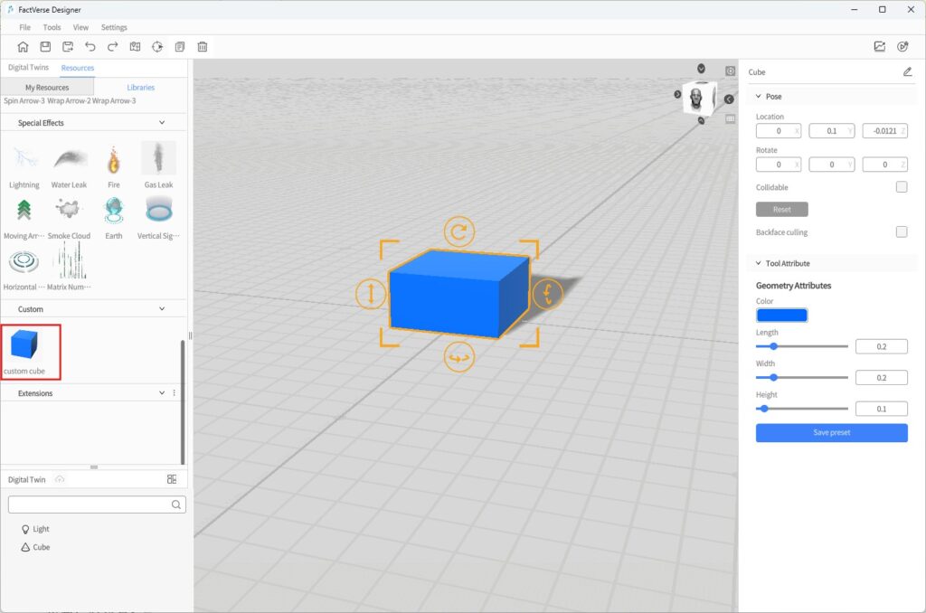
You can save tools with adjusted parameters as custom presets, making it easy to reuse them when building future scenes or editing digital twin templates. All custom tools appear in Resources > Libraries > Custom.
Add a Custom Tool
Steps
- In Resources > Libraries, select a tool and place it in the scene area.
- Adjust its attribute parameters as needed.
- After modifying the parameters, click the Save Preset button in the Attribute Panel.
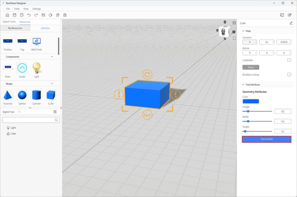
- In the pop-up naming window, enter a name and click OK.
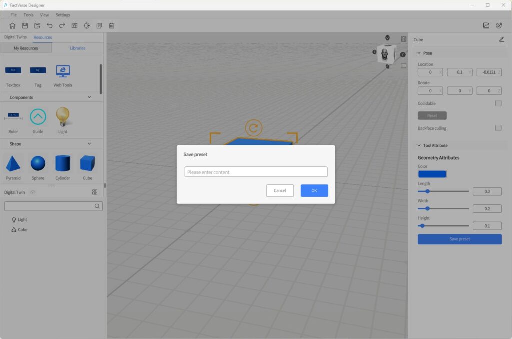
- The tool will now appear under Resources > Libraries > Custom as a custom preset, with the same icon as the original tool.
Edit and Manage Custom Tools
Update Existing Presets:
- From the Libraries, select a custom tool and place it in the scene area.
- Adjust its attribute parameters as needed.
- Click the Save Preset button.
- In the naming window, enter the same name as the existing preset.
- In the confirmation dialog, click Ok to overwrite the original preset.
Rename or Delete Custom Tools:
1. In Resources > Libraries > Custom, right-click the target tool to open the context menu.

2. Select Rename or Delete to manage the custom tool.
Path Mode
Path Mode is a function for defining movement trajectories of digital twins in a scene. By setting key points and their connectivity, you can construct a directed graph that constrains the movement range and direction of digital twins in the scene.
Path Mode applies to the entire scene. The constructed path graph can be shared by multiple digital twins, enabling behaviors such as AGV driving and robot patrolling.
Key Concepts
Concept | Description |
Key Point | A path vertex created in the scene, representing a positional node |
Connectivity | The connection relationship between key points, with direction options (one-way / two-way) |
Path | A sequence of connected key points forming a route for twins to follow |
Construction Mode
Construction Mode is used to add new path key points in the scene and define connectivity.
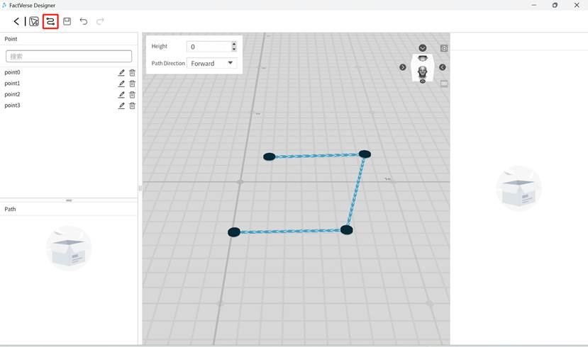
Steps
- After entering Path Mode, click the Path Mode button
 in the toolbar.
 - In the scene, click anywhere to add the first point. Move the mouse and click again to add the second point, automatically generating a connecting line.
- Continue adding key points, and the system will automatically connect them according to the default direction setting.
Path Mode Settings
To improve efficiency, you can configure default parameters in the upper-left corner of the scene:
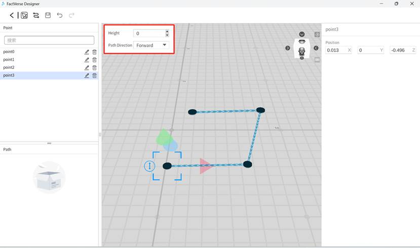
Parameter | Description |
Height | Default Z-axis height of all newly added points in the scene |
Path Direction | Set the direction between points: forward, reverse, or bidirectional |
Select Mode
Select Mode is used to adjust existing points or the overall view, without creating new points.

Instructions
- Adjust View: Drag the mouse to rotate or pan the scene view.
- Modify Key Point Position: Click an existing point to move it, or edit its coordinates in the Attribute Panel.
- Edit Connection Direction: Select a line between two points, then in the Attribute Panel click the direction icon to toggle between forward, reverse, and bidirectional.
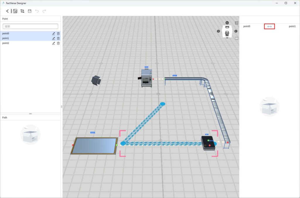
Basic Path Construction Workflow
- In the Scene Editor toolbar, click the Path Mode button
 to enter Path Mode.
 - Switch to Construction Mode, and click positions in the scene to add key points as needed.
- The system automatically connects the points based on default settings.
- Switch to Select Mode, then select key points or lines to adjust positions or directions.
- In Select Mode, clicking on points or lines lets you modify their position or connection direction.
Later, in the Behavior Tree, you can bind digital twin behaviors to path nodes to achieve complex motion control.

Positioning Mode
When creating a digital twin scene, FactVerse Designer automatically generates a marker at the (0, 0, 0) location in the scene. Users can scan this marker in DataMesh One while playing the scene to accurately place the digital twin scene at the target location in the physical environment.
FactVerse Designer offers positioning editing features, allowing users to modify, add, or delete markers as needed, or use reference models to assist in scene editing.
Edit Markers
In the Scene Editor, click the Positioning Mode button![]() in the toolbar to enter the Positioning Mode.
in the toolbar to enter the Positioning Mode.
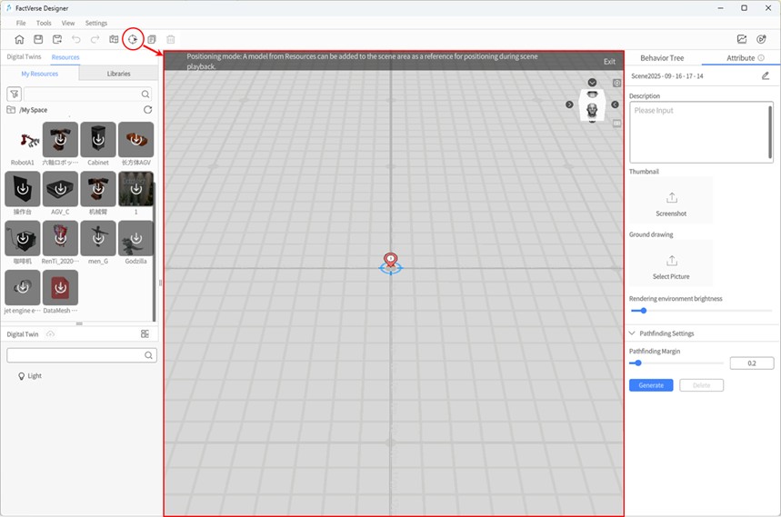
Edit Marker: In the element list (showing all markers and reference models), select the marker you want to edit. The attribute panel will display details such as:
- Position: Adjust the 3D location of the marker by modifying the position parameters.
- Rotation (Y): Change the rotation angle of the marker around the Y-axis.
- Preset: Use the attribute panel to quickly set the marker’s direction (horizontal or vertical).

Add Marker: Without selecting any element, click the Add Marker button in the attributes panel to add a new marker to the scene. The marker will automatically be numbered. You can add up to 20 markers per scene.

Delete Marker: Select the marker you want to remove, then click the delete button in the element list to delete it.
Add Reference Model
In a digital twin scene, you can use a reference model to help with scene editing and positioning.
Here’s how to add a reference model:
- Enter Positioning Mode: In the scene editor, click the “Positioning Mode” button
 in the toolbar.
 - Add Reference Model: Place a reference model in the scene to assist with scene editing and positioning.
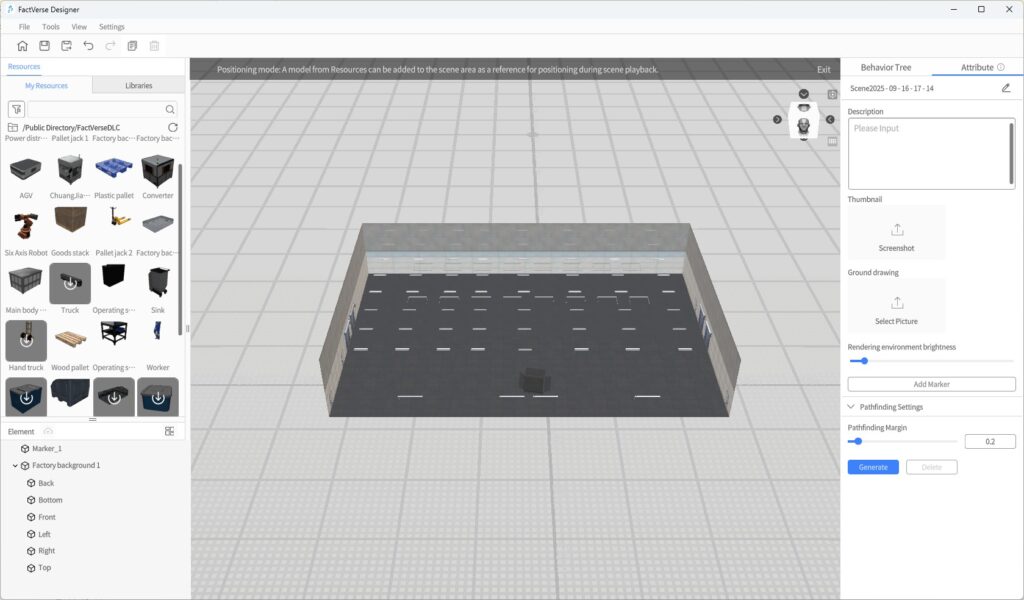
- Exit Positioning Mode: Click the “Exit” button to leave Positioning Mode.
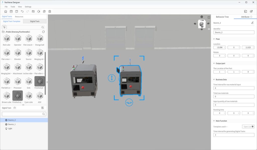
- Assist in Positioning Other Elements: Use reference models to help align other digital twins or elements in the scene with the actual physical environment.
Business Data Dashboard
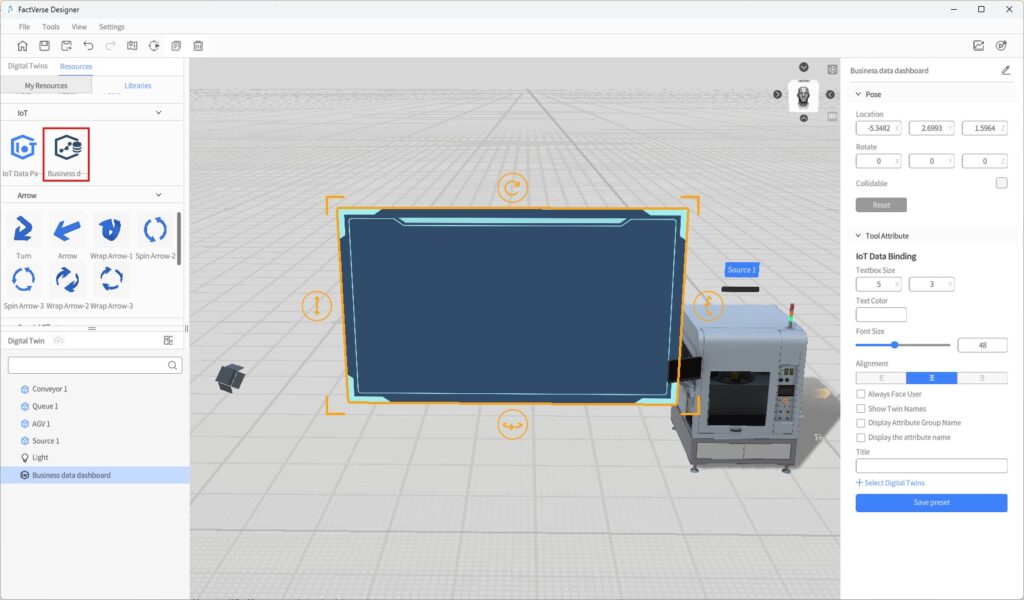
The Business data dashboard can be used to display real-time IoT data and simulated data. Users can select data in the attribute pane, and set text color, font size, and data prefix.
The following are the general steps to bind simulated data:
- Place the Business Data Dashboard tool into the scene.
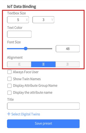
- Select the business data dashboard, and configure its font size, text color and alignment in the attribute pane.
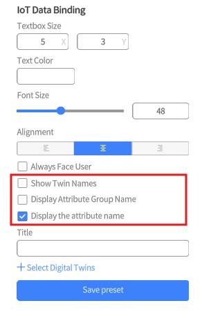
- Choose the content to display, such as the attribute names of digital twins.
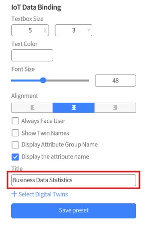
- Set the title of the dashboard.
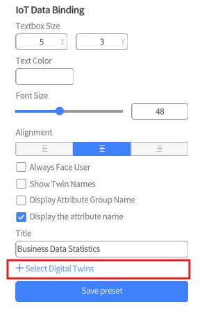
- Click on +Select Digital Twins.
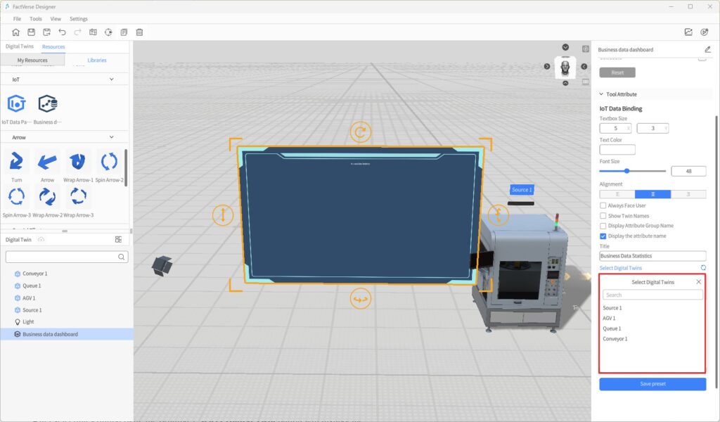
- After clicking + Select Digital Twins, a list of digital twins in the scene will appear. You can search for digital twins by name. In the list of selected digital twins, find the digital twin you want to bind and click to select it.
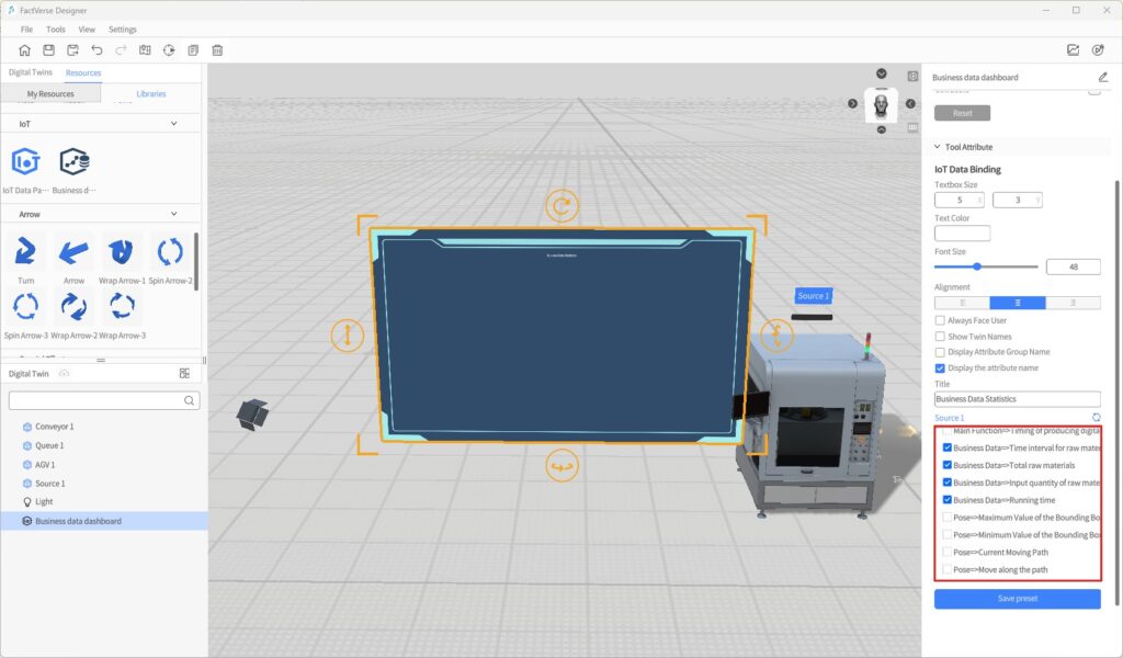
After selecting a digital twin, the original + Select Digital Twins button will display the name of the chosen digital twin. Clicking on this name will bring up the list of digital twins for reselection.
- After selecting a digital twin, the attributes of the digital twin will be displayed below the digital twin ‘s name. Click to select the attribute data you want to display.
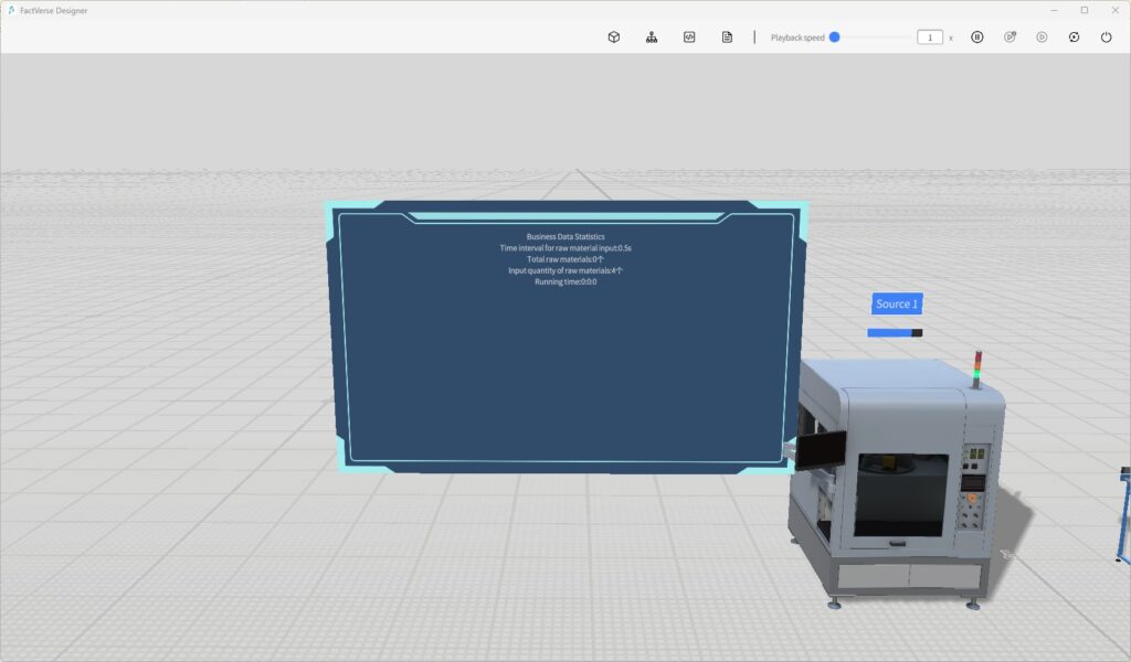
- Click the Debug Playback button
 in the upper right corner of the page to preview the effect.
Edit Scene Courseware
Target Users: Instructors in enterprises
Objective: In FactVerse Designer, bind courseware to a scene, assign digital twins to roles, and edit the logic of custom questions, including triggers, success/failure conditions, and scoring rules.
Courseware Editing Workflow Overview

The process of editing scene courseware consists of two main phases:
Phase 1: Prepare Courseware (in FactVerse Platform)
- Create scene courseware and configure basic information (name, duration, passing score, etc.).
- Add questions (supports single-choice, multiple-choice, and custom questions).
- Publish the courseware for further binding and editing in Designer.
- Create a training group and assign learning and exam tasks to trainees.
Alternatively, training groups can be created later in the platform after courseware editing is completed in Designer.
For details on preparing courseware, see the Learning Management section of the FactVerse Platform User Manual.
Phase 2: Edit Courseware (in FactVerse Designer)
- Bind courseware to a scene.
- Bind roles to digital twins.
- Edit the logic of custom questions.
- Run and validate whether the question settings are correct.
Bind Courseware to Scene
Binding Rules:
- Each courseware can be bound to only one scene.
- Once bound, the scene cannot be changed.
Steps
Note: It is recommended to use the same version of Designer that was used when creating the courseware. Opening courseware created in a newer version with an older Designer may cause compatibility issues due to question structure updates, preventing some content from displaying or being edited properly.
- On the Home Page, click Open Courseware and select the target courseware.
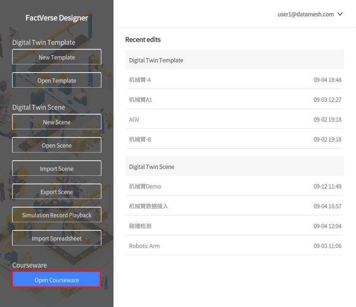
- If no scene is bound, choose a scene for binding, or click New Scene to create a scene and follow the digital twin scene building workflow before binding.

Bind Digital Twins to Roles
Once a digital twin is bound to a role in the courseware, it becomes the object that the role must operate during the exam and is associated with the corresponding question logic.
During the exam, candidates must select their role to enter the scene. The system automatically links them to the digital twin bound to that role, enabling role-specific operations and answering tasks.
Examples:
- Role = Forklift Operator, Digital Twin = Forklift → The operator must complete driving-related tasks.
- Role = Technician, Digital Twin = Control Panel → The technician must complete repair-related tasks.
Steps
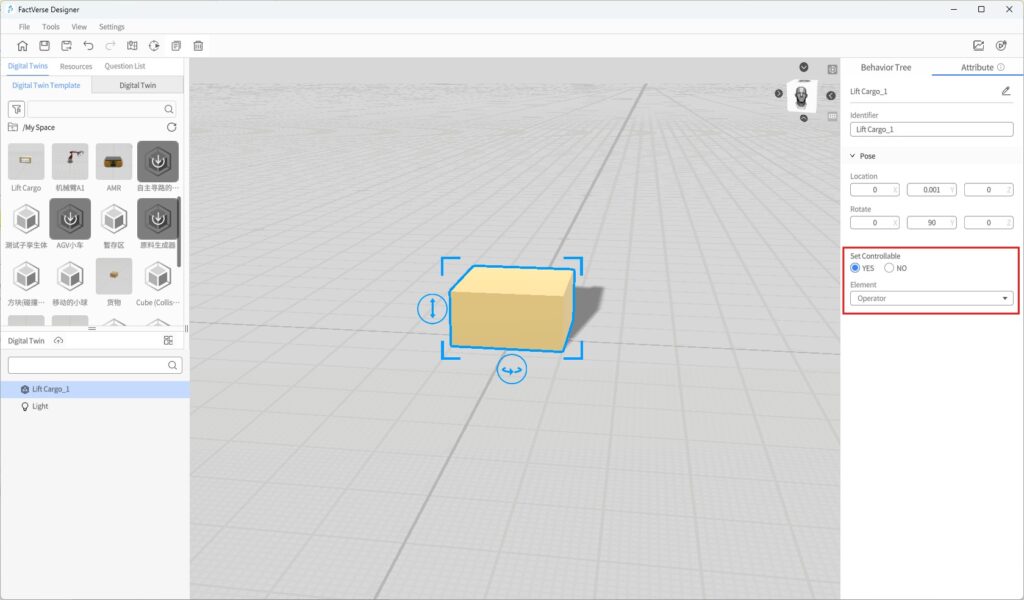
- In the scene area, select the target digital twin.
- In the Attribute Panel, set Assign Role to Yes and choose the corresponding role.
Edit Custom Questions
Custom questions can be added in two ways:
- In FactVerse Platform: Only basic information (question stem, role, etc.) is created, without logic or scoring.
- In Designer: Create or edit to define triggers, success/failure conditions, scoring rules, etc.
Configure Custom Question Logic
- Set Judgment Logic
Custom questions support defining trigger, success, and failure conditions to enable automatic task initiation, completion checks, and violation detection.
Condition Type | Description |
Trigger Condition | Defines when the question starts, based on twin states, interactions, or external events. |
Success Condition | Determines the standard for completing the task, usually based on results and twin states. |
Failure Condition | Defines when the task fails or an error occurs, such as collisions or invalid operations. |
Example: Vehicle Obstacle Avoidance Training
- Scenario: The candidate drives a vehicle out of a parking lot while avoiding obstacles.
- Trigger Conditions:
- Vehicle approaches the exit: Use Compare Distance to check if the distance between the vehicle and the exit is less than 2m.
- Vehicle has not yet passed the exit: Use Compare Two Attribute Values with “Pass Status = 0”.
- Success Conditions:
- No collision: Use Compare Two Attribute Values with “Collision detection result = 0”.
- Vehicle successfully exits: Use Compare Two Attribute Values with “Pass Status = 1”.
- Failure Condition:
- Collision occurs: Use Compare Two Attribute Values with “Collision detection result = 1”.
- Trigger Conditions:
- Configure Scoring Method
After completing a custom question, the system calculates the score in the following ways:
Scoring Type | Description |
Direct Score | Award a fixed score upon task completion (e.g., 100 points). |
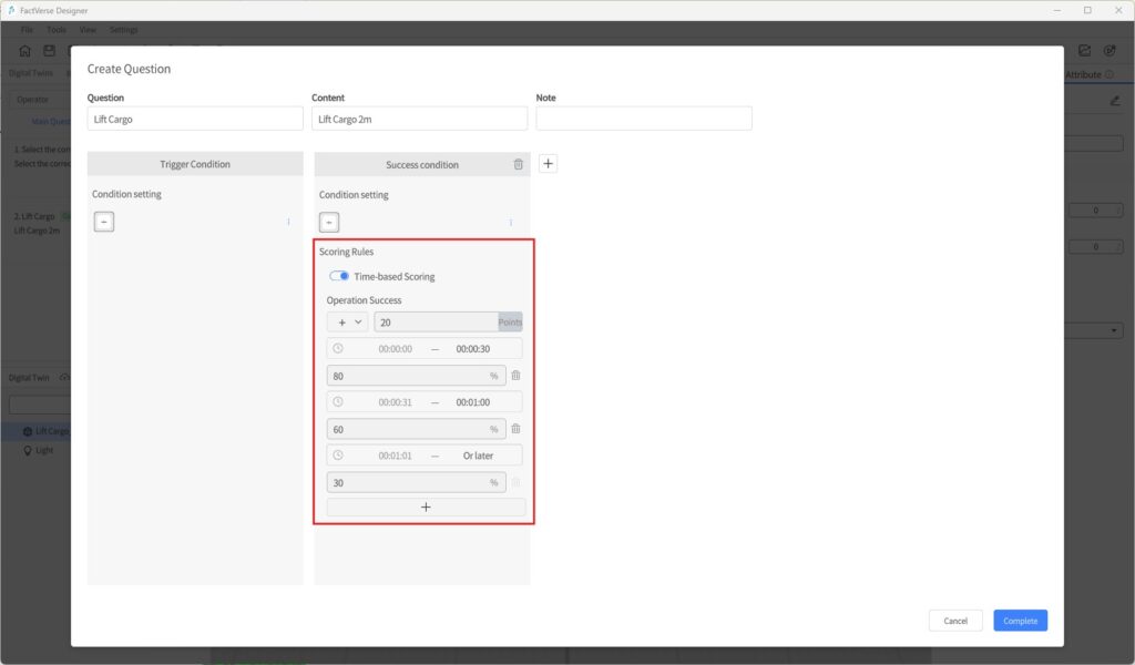
Time-based Score | Score proportionally based on completion time within preset time segments. |
Example:
- Task success = 100 points.
- Time segment weight = 80%.
- Actual score = 100 × 80% = 80 points.
If Time-based Score is not enabled, Direct Score is used by default.
To enable Time-based Scoring, check the option in the configuration panel and define the percentage for each time segment.
Editing Steps
- Configure interaction logic: Before editing the question, ensure the scene includes relevant interactions (e.g., digital twin attribute changes, movements).
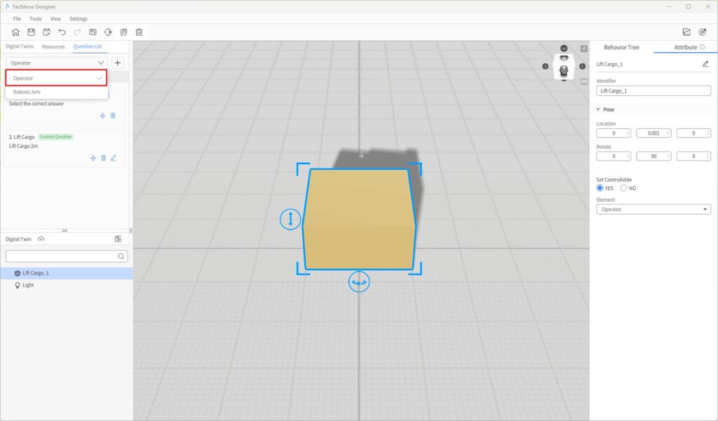
- Display role-related questions: In the left-side question list, select a role to expand its questions.
- Add a custom question:
- If not created in the platform, click + > Custom Question in Designer.
- If already created in the platform, skip this step.
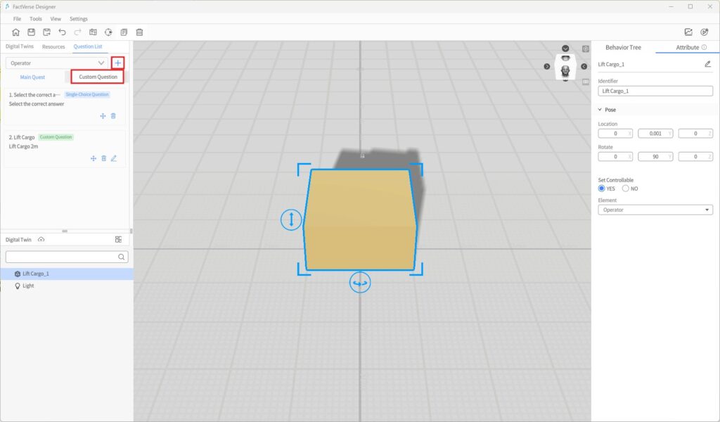
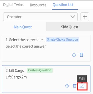
- Edit question logic: In the question list, click the Edit icon next to the question to open the editing window.
- Configure conditions and scoring rules: In the editing window, set trigger, success/failure conditions, and scoring methods (direct, time-based, etc.).
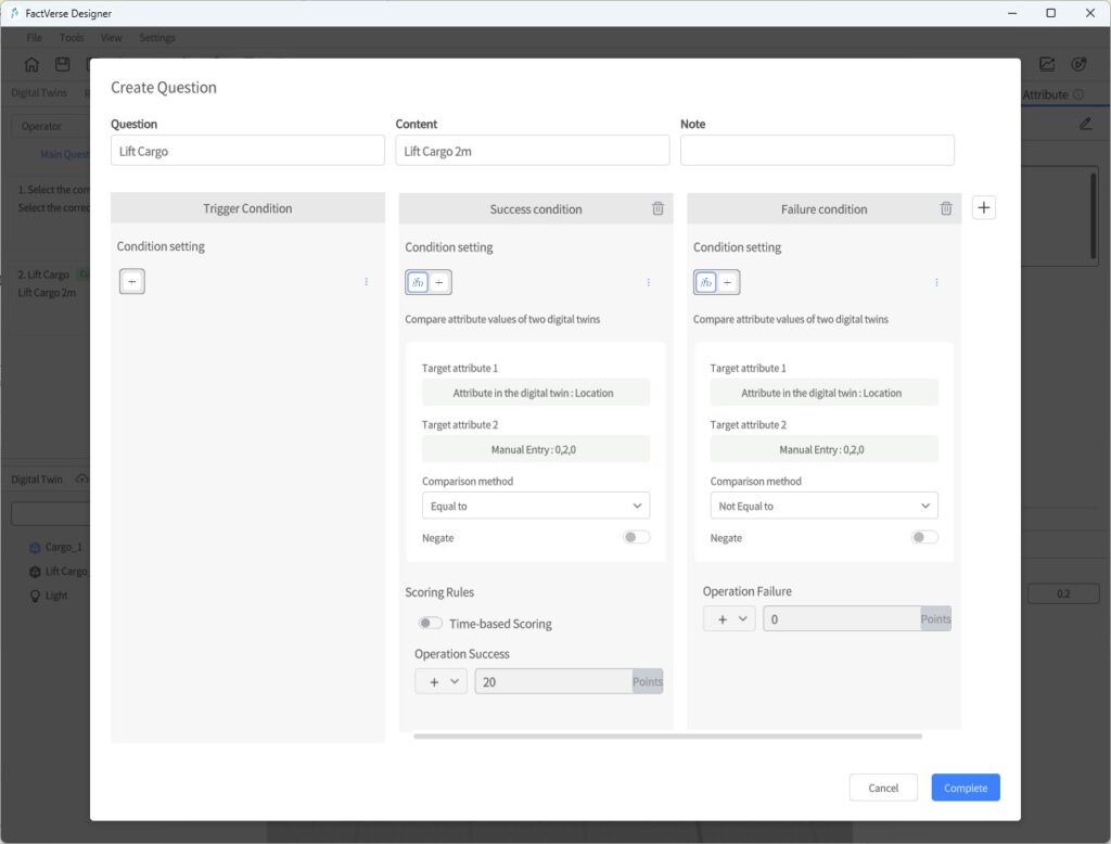
- Save the question: After configuration, click Complete to save the settings.
Run and Verify
You can simulate candidate operations to validate whether the logic and scoring mechanisms work as expected.
Steps
- Play Courseware: Click the Debug Playback button in the toolbar to enter courseware simulation mode. In the role list, select the answering role.
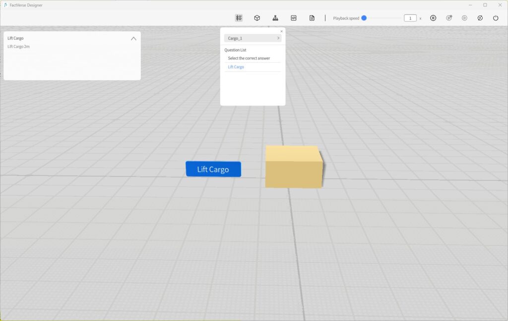
- Test the questions: In the playback interface, simulate answering and check if the settings are correct:
- Choice questions: Verify that single-choice and multiple-choice questions work correctly.
- Custom questions: Perform defined interactions (e.g., clicking or dragging a twin) to check triggers.
- Judgment logic:
- ¡ Correct operations should be judged as success.
- ¡ Incorrect or invalid operations should be judged as failure.
- Scoring validation: Ensure scores follow the defined rules (direct score, time-based score, etc.).
- Adjust in the editor if issues occur: If abnormal triggers, inaccurate judgments, or scoring errors are found, return to the editing interface, adjust the settings, and re-validate.
Collision Detection
The Collision Detection feature is used to determine whether digital twins physically contact each other during simulation. This helps validate the rationality of scene design and the safety of operation paths. By using collision detection, users can quickly identify potential design flaws, optimize equipment layout and movement paths, and reduce accident risks.
Key Steps
To implement collision detection, configure the following:
- Specify the digital twin responsible for outputting collision results
- Enable Collidable in its template.
- Add the Collision Detection preset structure in its template. This structure records real-time collision data, including collided object, role, and timestamp.
- Configure other objects (digital twins or models) to participate in collision
- In the scene, enable Collidable for these objects so they can interact with the reporting twin.
- Run simulation and analyze results
Notes:
- All objects (digital twins / models) must have Collidable enabled.
- Only digital twins with the Collision Detection preset structure can output and record collision results.
- Multiple detection objects can exist in a scene, but at least one twin must be responsible for recording the results.
Example
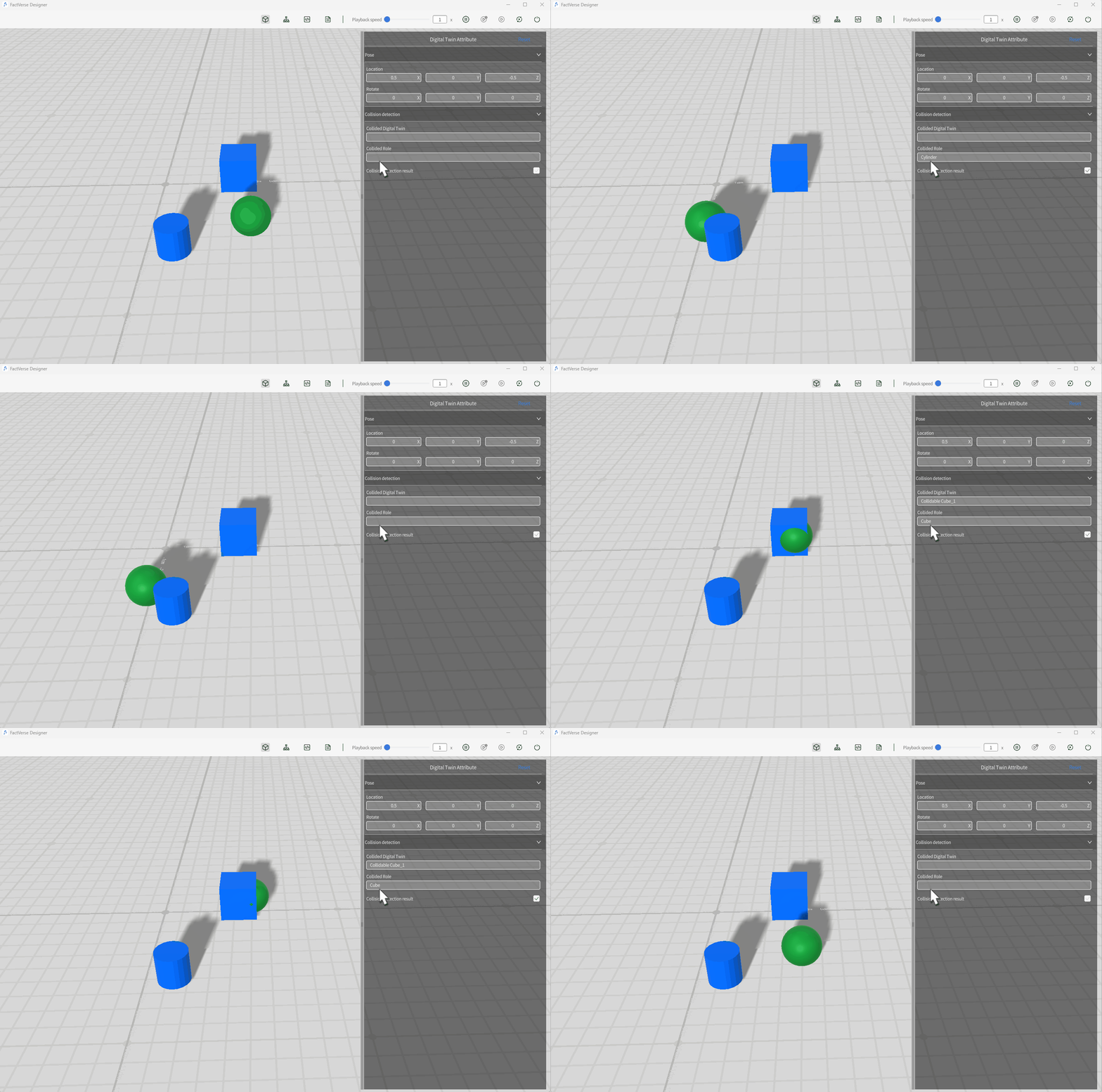
This example simulates a moving ball twin colliding with a stationary cube and cylinder, to verify that collision detection works and to observe how collision information is updated in the twin’s attributes.
Steps
- Create a movable ball template:
- Refer to the Moving Ball section and create a ball template with movement behavior.
- Enable collision participation for the ball:
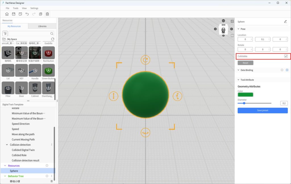
- Select the ball in the scene, and in the Attribute Panel, check Collidable. Once enabled, the ball will participate in collision detection handled by the physics engine.
- Add the Collision Detection preset structure to the ball template:
- In the ball template, add the system preset Collision Detection structure to capture collision states.
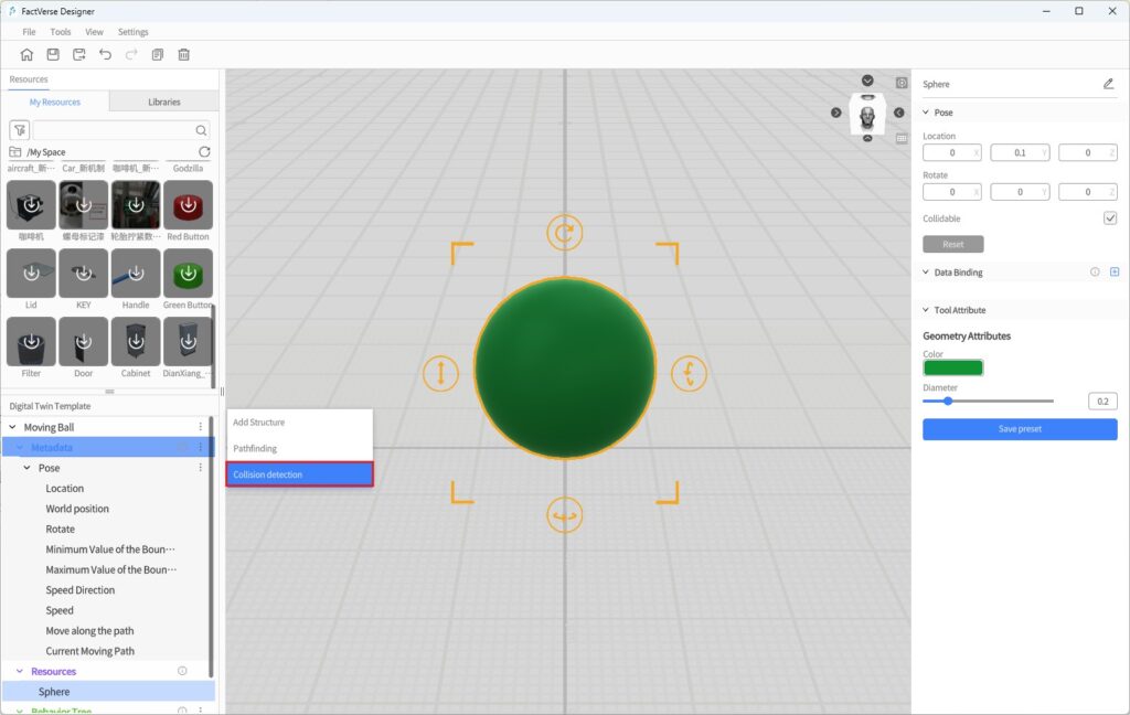
This preset structure includes the following attributes:
| Attribute Name | Type | Description |
| Collided Digital Twin | string | Records the name of the twin that collided with the current twin |
| Collided Role | string | Records the role bound to the collided twin |
| Collision Detection Result | bool | true if a collision occurs, false if no collision |
- Save the ball template: After configuration, click Save to store the template.
- Create a cube template and enable collision participation:
a) In the Template Editor, create a new cube template and place a cube model.
b) In the Attribute Panel, check Collidable.
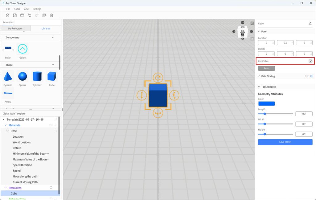
c) Click Save to store the template.
- Build the test scene:
a) Create a new test scene.
b) Place the Moving Ball and Cube twins in the scene.
c) Optionally add a static cylinder model to test multiple collision targets.
d) Adjust positions so that the cube and cylinder are placed along the ball’s movement path.
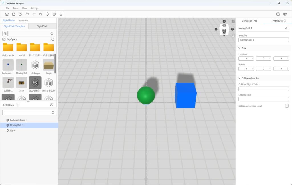
- Preview playback:
a) Click the Debug Playback button in the toolbar to run the scene.
b) Select the ball twin and open the Attribute Panel.
c) Observe whether the fields Collided Digital Twin and Collided Role correctly display the names of the collided objects.
- Analyze simulation results:
- For detailed analysis, refer to the Collision Analysis Table.
Pathfinding
The Pathfinding feature is based on 3D path simulation, collision detection, and safety range modeling. It provides digital twins with automated path planning and obstacle avoidance capabilities. It is suitable for complex scenarios such as AMR (Autonomous Mobile Robot) navigation and personnel safety path simulations.
Application Scenarios
Scenario Type | Description |
Logistics and Operation Optimization | Quickly plan the shortest path for equipment or personnel to reduce energy consumption and path waste. |
Risk Prediction and Avoidance | Detect potential risks such as collisions or deadlocks through path simulation, and optimize layouts and workflows. |
Terminology
Term | Description |
Pathfinding | Only digital twins with the Pathfinding preset structure can execute the Pathfinding behavior tree node. |
Safety Range Box | A cylindrical wireframe that represents the physical safety boundary of a twin during pathfinding, used for obstacle avoidance and path calculations. |
Safety Range Diameter/Height | Size parameters of the safety range box, configurable in the Autonomous Pathfinding structure (unit: meters). |
Pathfinding | A behavior tree node that drives a twin to follow the optimal path planned on the pathfinding surface. |
Pathfinding Surface | Defines the navigable area for digital twins; paths are planned only within this surface. |
Pathfinding Margin | The buffer distance between participating digital twins and the edge of the generated surface, preventing collisions along boundaries. |
Key Steps
Autonomous pathfinding usually consists of four stages:
- Configure the Digital Twin
- Add the Pathfinding structure to the target twin template.
- The system automatically generates a Safety Range Box, and its diameter and height can be set in the Attribute Panel.
⚠️ Note: Pathfinding and Collidable cannot be enabled simultaneously. To include a digital twin in pathfinding, enable only Pathfinding, otherwise the digital twin cannot move.
- Configure the Pathfinding Environment in the Scene
- Add a ground model for the pathfinding surface and enable Collidable.
- Place digital twins with Pathfinding into the scene.
- Add obstacles (also with Collidable enabled).
- Generate the Pathfinding Surface
- In Scene Properties → Pathfinding Settings, configure the offset distance (default: 0.2 m).
- Click Generate to automatically construct the navigable area.
- If the scene is modified, click Regenerate.
- Validate Pathfinding
- Use Simulation Review to generate and replay simulation records.
- In the dashboard, check the Path Analysis Table and Collision Analysis Table, overlaying paths in the scene.
- Verify whether collisions, failed avoidance, or abnormal detours occur.
- If necessary, adjust pathfinding settings, safety range, or obstacle positions, regenerate the pathfinding surface, and re-validate.
For details, see Simulation Review → Simulation Path Visualization .
Example
This example shows how to configure a twin for autonomous pathfinding:
- Open Template Editor: Open the target twin template in the Template Editor.
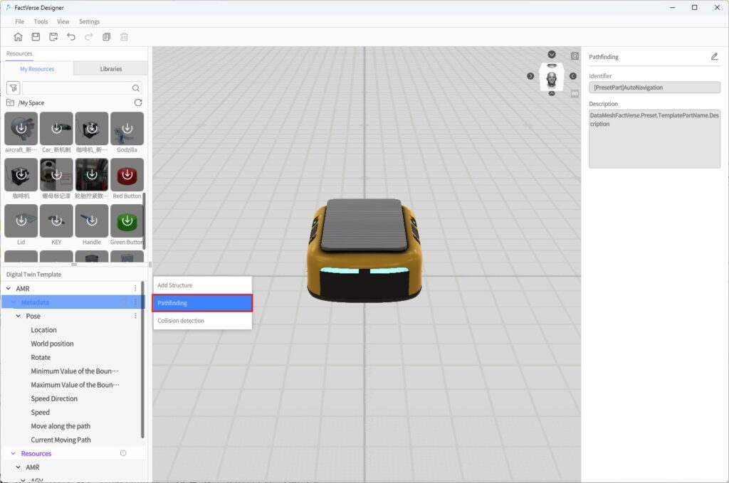
- Add Pathfinding Structure: Add the Pathfinding The system generates a fixed Safety Range Box at the template’s center.
- Set Safety Range Parameters: In the Attribute Panel, configure the safety range diameter and height.
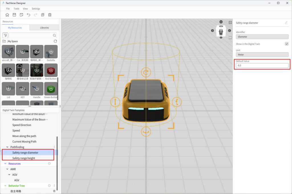
Attribute Name | Type | Default | Editable | Visible |
Safety Range Diameter | double | 0.5 m | Yes | Yes |
Safety Range Height | double | 0.5 m | Yes | Yes |
- Configure Behavior Tree Node:
a) Create a new behavior tree and add a Pathfinding node in the Behavior Tree Editor.
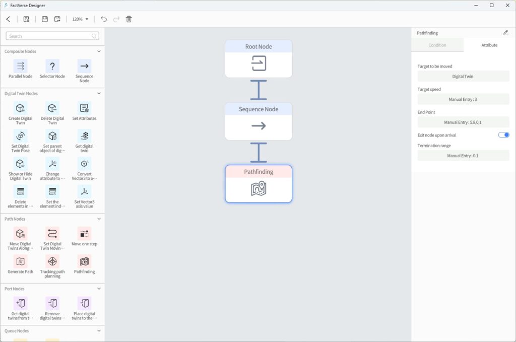
b) Configure the node’s attributes:
Setting | Description |
Target to Move | Select the digital twin that will perform pathfinding |
Target Speed | Maximum movement speed (excluding acceleration/deceleration) |
End Point | Set the endpoint (supports digital twins, ports, or manual entry) |
Exit Node upon Arrival | Whether to automatically exit this node after reaching the endpoint: |
Termination Range | Distance threshold to consider the endpoint reached (unit: meters) |
- Save Template: Click Save to store the template and exit the Template Editor.
- Configure Pathfinding Environment in the Scene:
a) Add a ground model and enable Collidable.
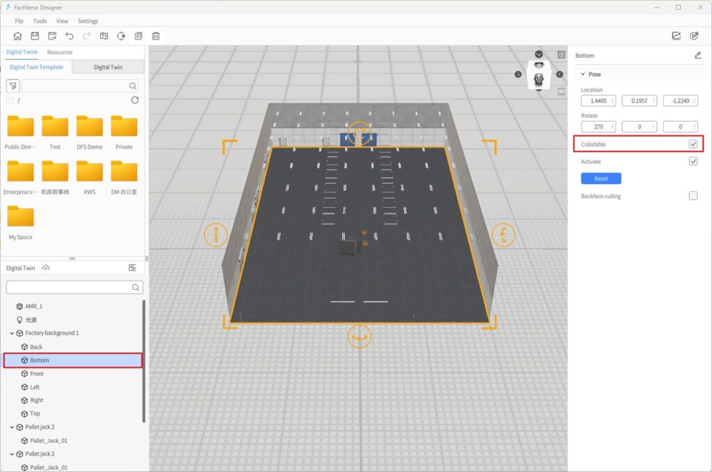
b) Place digital twins with Pathfinding into the scene.
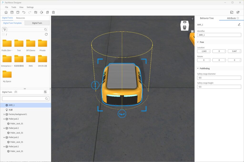
c) Add obstacles of any shape and enable Collidable.
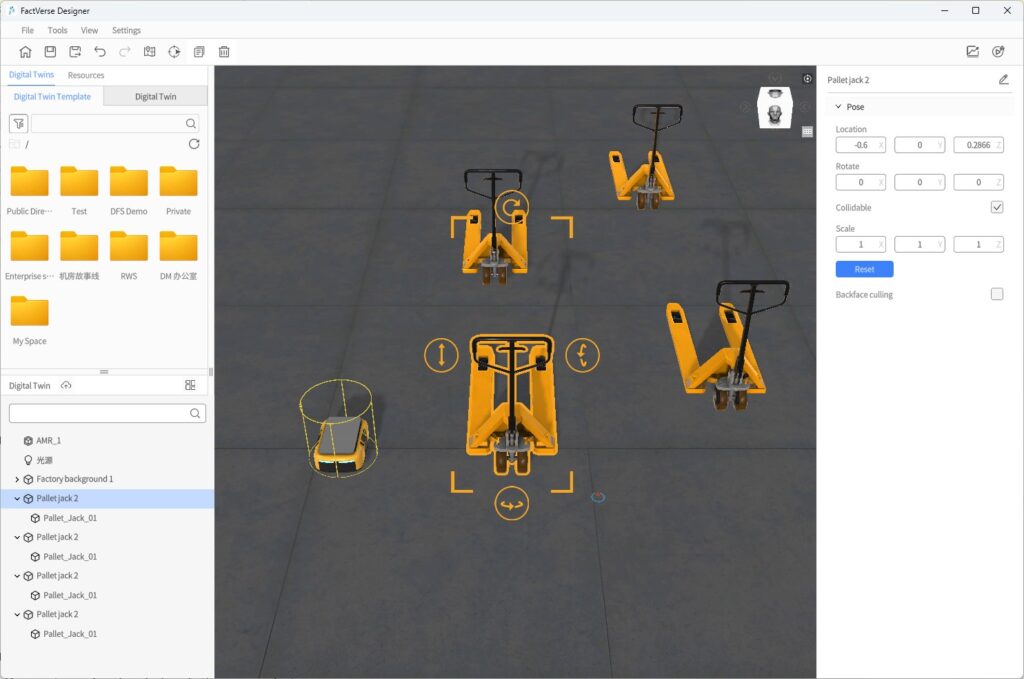
- Generate Pathfinding Surface:
a) Configure the offset distance in Scene Properties.
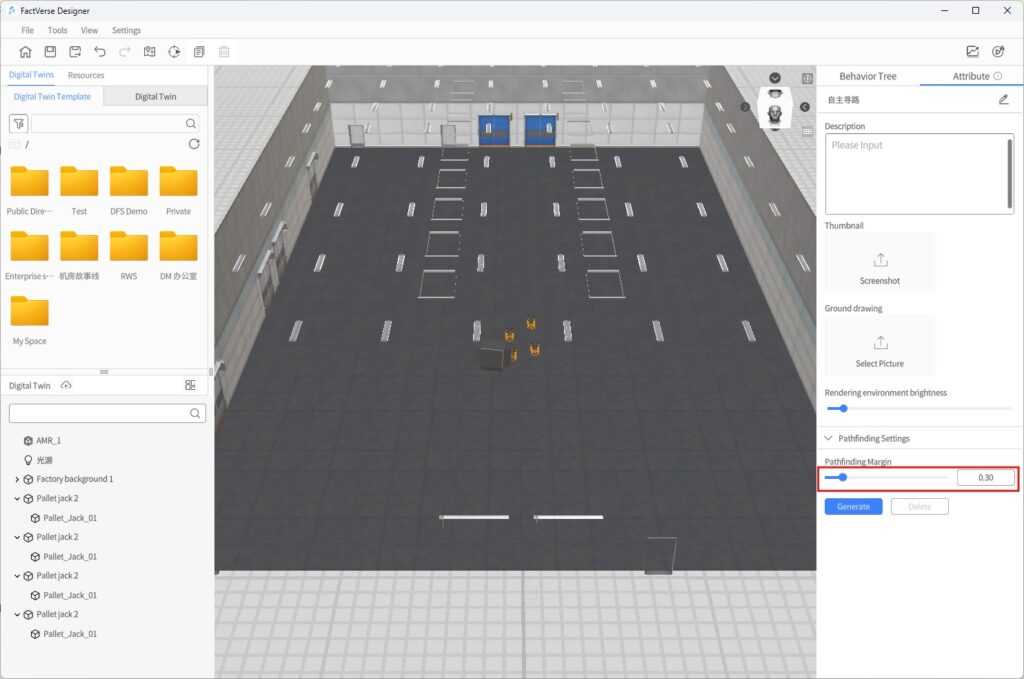
b) Click Generate to create the navigable area.
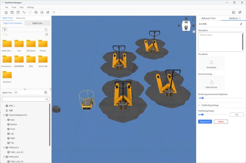
- Validate Pathfinding:
a) Generate and upload simulation records.
b) Review simulation paths.
c) Adjust parameters based on the results and optimize if needed.
Simulation Review and Data Analysis
In Designer, you can use Simulation Review together with the DFS Dashboard feature to collect and analyze simulation data of equipment under different operating conditions. Through 3D scene playback and multi-dimensional data visualization, you can better understand simulation processes, evaluate performance, and guide further optimization.
⚠️ Note: This feature is currently supported only on Windows systems.
Objectives supported by this feature:
- Collect operating parameters (e.g., speed, temperature, pressure), production progress (e.g., completed quantity, production time), and fault data.
- Generate visual charts to clearly present simulation results.
- Optimize parameter configuration based on analysis results to continuously improve process design.
- Improve equipment efficiency and resource utilization, reduce production costs, and enhance quality and delivery capability.
Basic Workflow
The complete workflow of simulation review and analysis consists of three stages:
- Build the scene: Construct a scene containing key logic such as collision detection, pathfinding, or production processes.
- Generate and upload simulation records: During simulation runs, generate simulation data and upload the records to the DFS platform.
- Conduct simulation analysis: In the Simulation Review interface, work with the DFS dashboard to:
- View multi-dimensional data charts.
- Replay 3D simulation processes to understand equipment behavior.
- Check the Collision Analysis Table to identify risk events.
- Visualize paths to optimize scheduling and layout.
Generate and Upload Simulation Records
Simulation records preserve simulation run results and provide the basis for later analysis.
Steps:
- Open the target scene: Open the scene in which you want to generate a simulation record.
- Generate the simulation record:
a) Click the Generate Simulation Record button![]() in the toolbar.
in the toolbar.
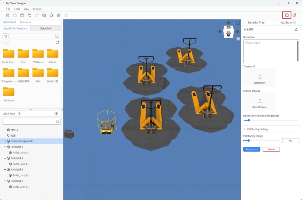
b) In the Generate Simulation Record window, configure the following:
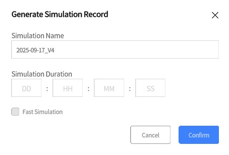
- Simulation Name: Default format YYYY-MM-DD_V1, max 30 characters.
- Simulation Duration: Format DD:HH:MM:SS, max value 99 per field, integers only.
- Fast Simulation:
- If checked, Simulation Duration is required. The system will generate results quickly.
- If unchecked, Simulation Duration is optional. The system will run in real time (1× speed).
- Special case: For simulations involving collision or pathfinding, fast simulation cannot be selected. Duration may be left blank; the system defaults to 1× speed.
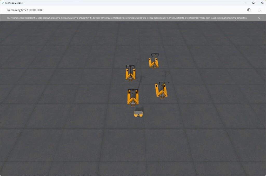
c) Click Confirm to start the simulation run.
(Tip: Close other large applications while running simulations for better performance)
- Upload the simulation record:
- Auto upload: If a duration was set, the system automatically uploads the record after the run.
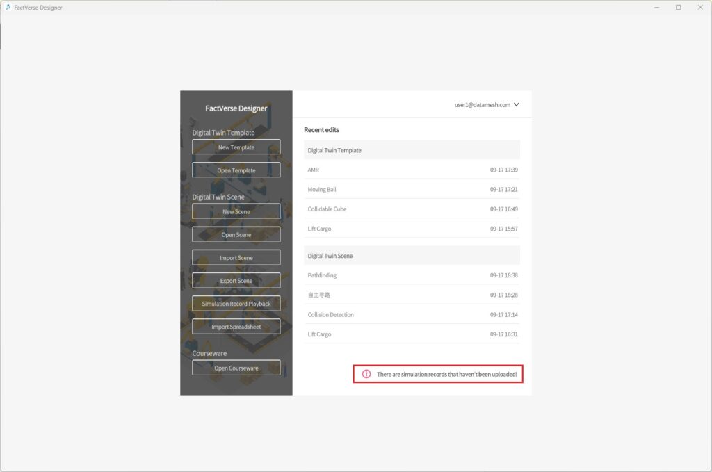
- Manual upload: If no duration was set, click the Exit button in the simulation window. In the prompt, select Yes to upload the record. If No is selected, after returning to the homepage you will see a reminder for unuploaded record. Click the reminder to upload.
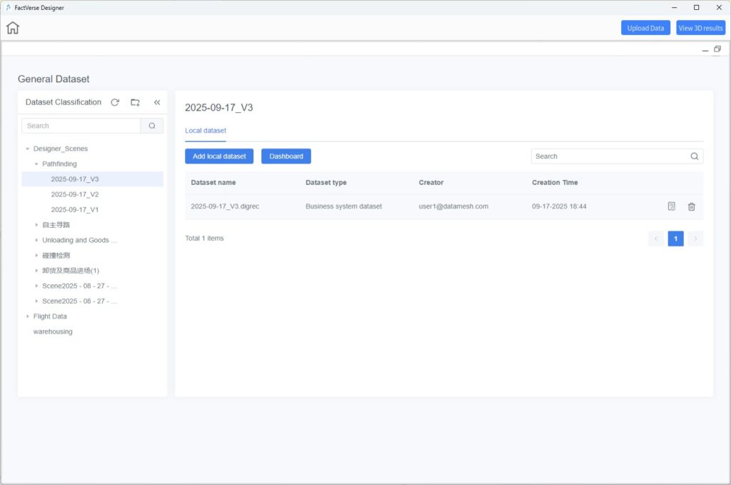
- Save location: Uploaded records are stored in DFS under the Designer_Scenes directory for the corresponding scene.
Simulation Review Interface
You can enter Simulation Review interface in two ways:
Method 1: Directly after upload
- In the completion prompt after uploading, click OK. The system automatically opens the DFS page.
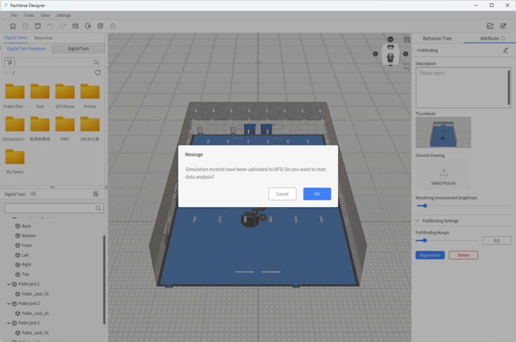
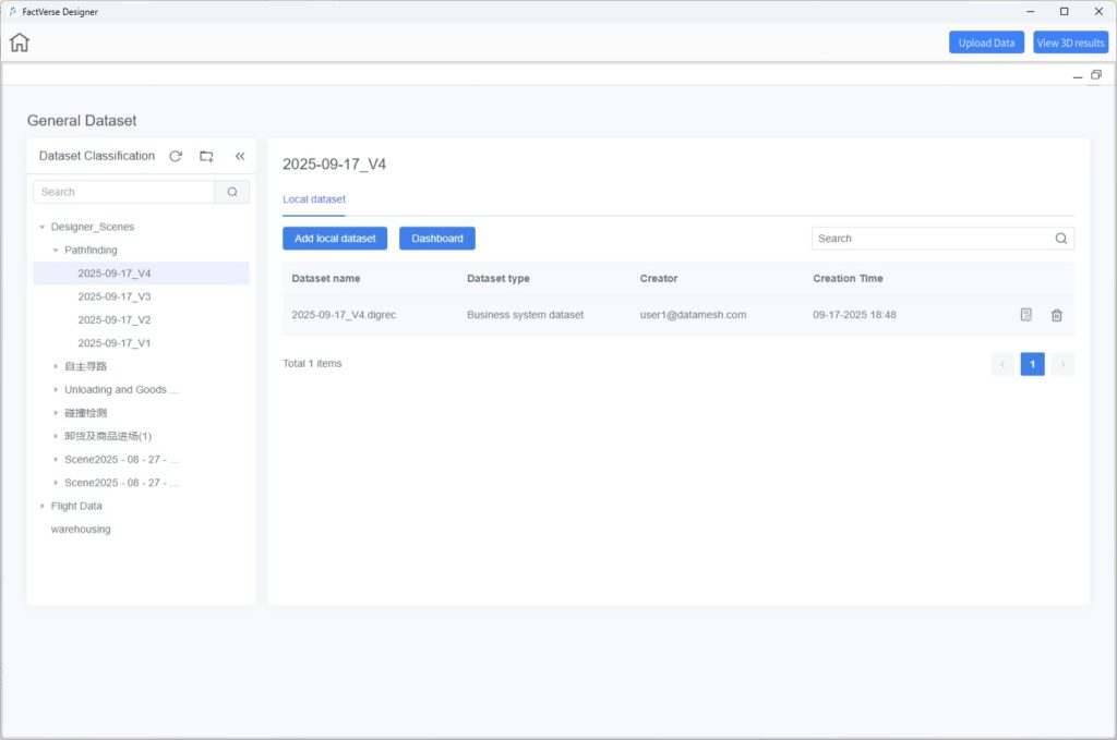
- The DFS page appears as a floating window above the Designer scene, maximized by default.
- If the scene has no dashboard configured: The page defaults to the newly uploaded dataset.
- If the scene has a dashboard configured: The page opens directly to the dataset’s dashboard.
Method 2: From the homepage
- On the homepage, click the Simulation Record Playback button to open the DFS dataset page.
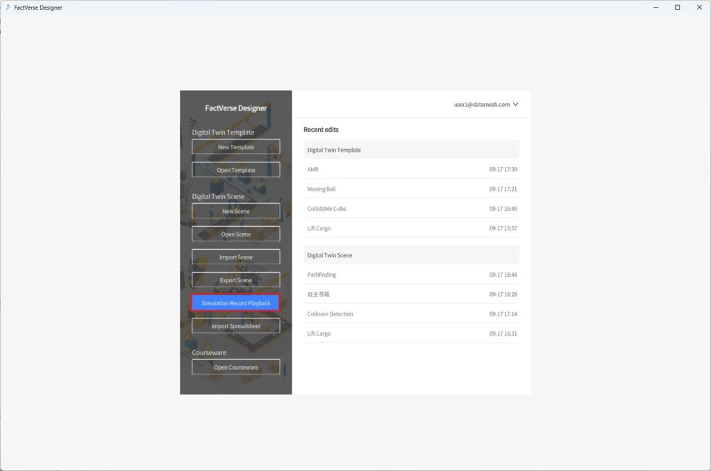
- Select a dataset to enter Simulation Review and perform actions such as viewing charts, dashboards, and 3D record playback.
View Data Analysis Charts
Charts provide an intuitive way to analyze simulation performance, identify bottlenecks, and find optimization opportunities.
Steps:
- Enter the Simulation Review interface.
- In the DFS window:
a) Click the target dataset to open its data page.
b) Configure and view generated charts and analysis results.
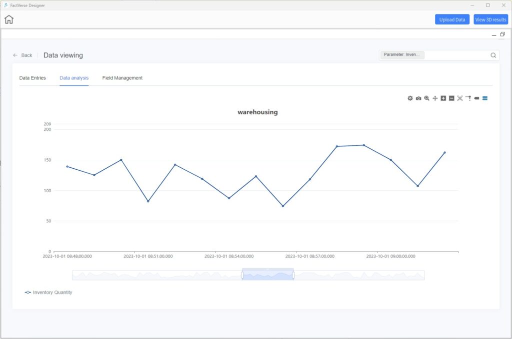
For details, see DataMesh FactVerse DFS User Manual → Dataset View.
Replay 3D Simulation Records
The replay function allows you to review the complete 3D simulation process for analysis and troubleshooting.
Steps
- Open the Simulation Review
- Click View 3D Results to load and replay the simulation record of the dataset.
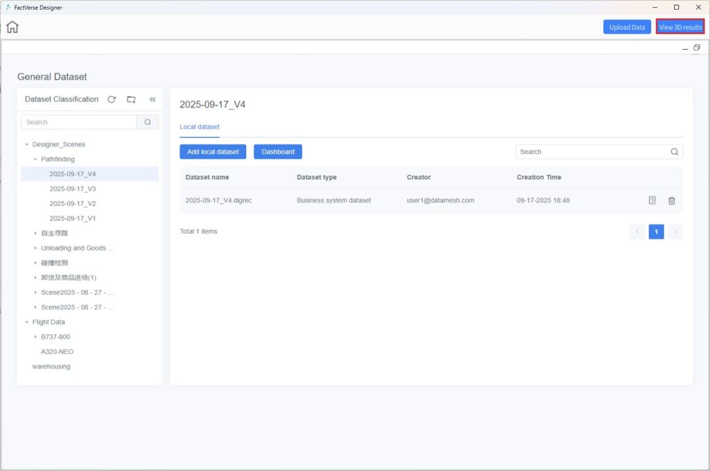
- Minimize the DFS window. The corresponding 3D simulation data will appear in the Designer
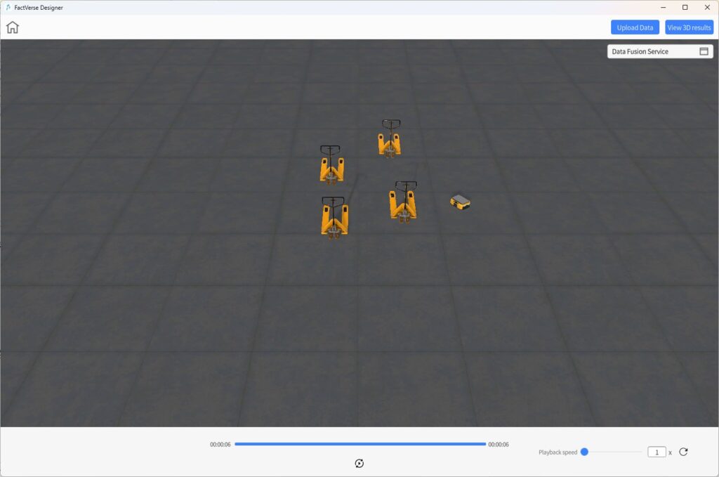
- Use the playback controls:
- Play / Pause
- Replay
- Speed: Up to 20× speed playback.
Dragging the progress bar or skipping to a specific time is not supported.
- Click on Data Fusion Services to reopen the DFS window for further data analysis or to switch datasets.
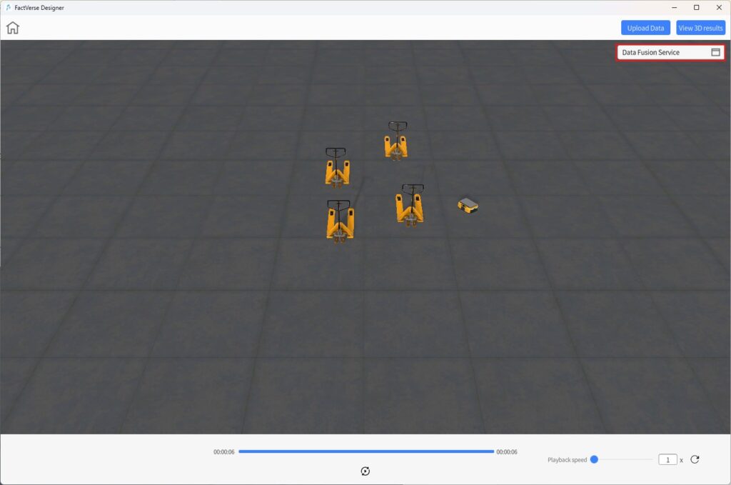
View Dashboards
Collision Analysis Table
The collision analysis table provides a quick overview of all collision events during the simulation. It helps users reproduce issues, optimize equipment layout, and refine motion paths.
Steps
- Open the Simulation Review interface.
- Configure the collision detection dashboard: In the DFS window, select the target dataset, configure the dashboard, and add the Collision Detection component. (See DFS User Manual → Configure Dashboard Components → Collision Detection.)
- View the Collision Analysis Table.
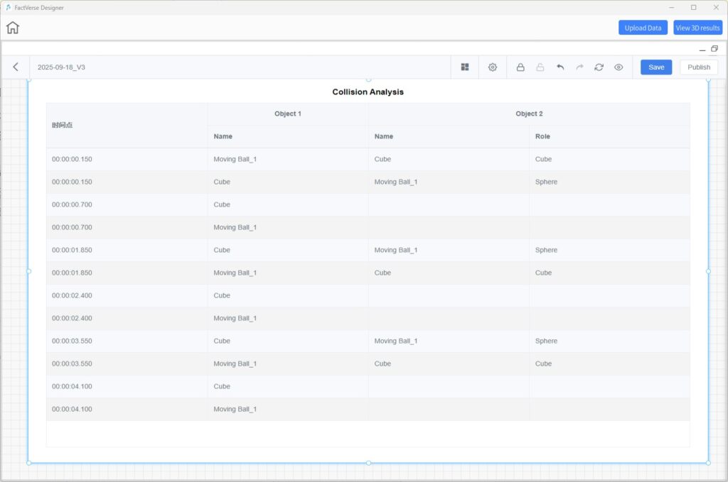
Table Description
The table records all collision events during the simulation, allowing quick identification of the time, objects, and roles involved.
| Timestamp (DD:HH:MM:SS) | Object 1 | Object 2 | Role of Object 2 |
| Specific time of collision | Name of the first colliding digital twin or model | Name of the second colliding object | Role of the object involved in the collisio |
Simulation Path Visualization
The simulation path visualization displays the full trajectories of moving equipment in the 3D scene. It helps users:
- Evaluate the efficiency and rationality of motion paths
- Identify potential areas for optimization
- Predict risks of collisions or congestion in advance
- Develop better scheduling strategies
Steps
- Open the Simulation Review interface.
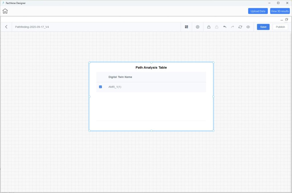
- Configure the path analysis dashboard: In the DFS window, select the target dataset, configure the dashboard, and add the Path Analysis component. (See DFS User Manual → Configure Dashboard Components → Path Analysis.)
- In the Path Analysis Table, select the digital twins whose paths you want to display.
- Click 3D Scene View, minimize the DFS window, and view the overlaid paths in the scene.
Notes
- Paths are displayed as static trajectories: a complete track formed by connecting all recorded path points.
- Multiple paths can be displayed simultaneously for comparison and analysis.
Scene Debugging and Testing
FactVerse Designer provides a Debug Playback mode for verifying scene logic, checking the execution of digital twin behavior trees, and supporting simulation data input and log output. This assists with development debugging and workflow optimization.
Debug Playback Interface
Click Debug Playback ![]() on the Scene Editor toolbar to enter Debug Playback mode.
on the Scene Editor toolbar to enter Debug Playback mode.
This mode allows you to run scene logic, debug behavior trees, send simulation data, and view real-time logs. It is designed for validating digital twin responses, behavior logic correctness, and interaction effects.
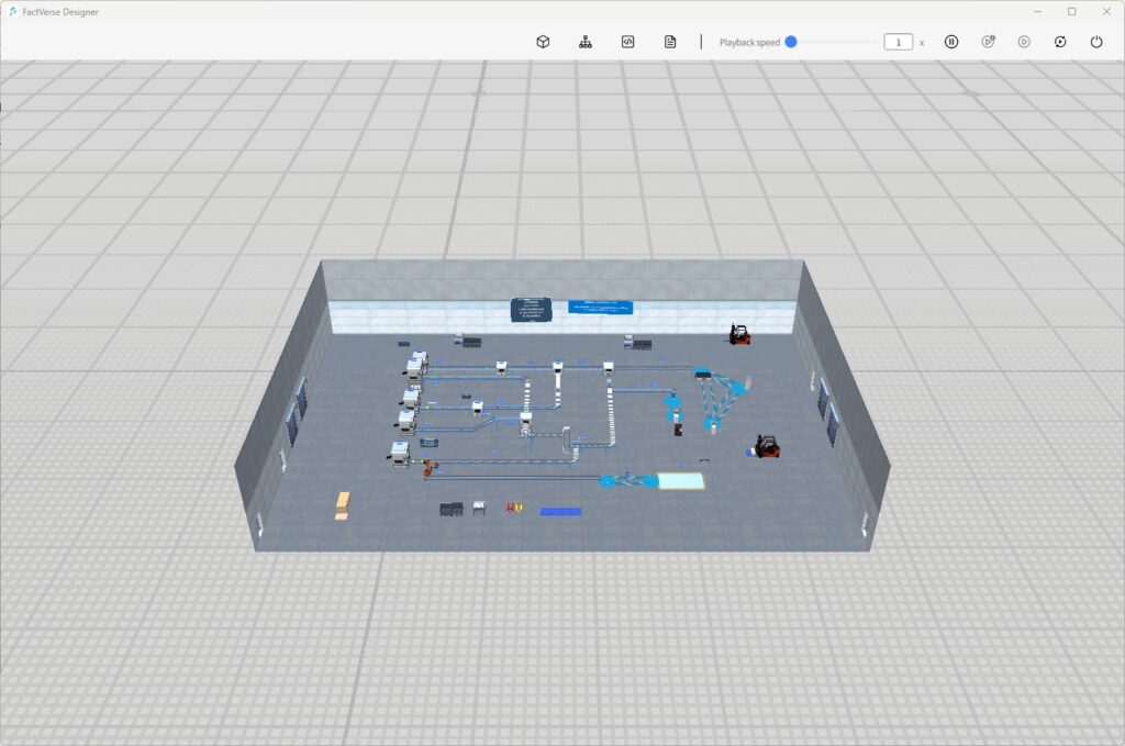
Toolbar Functions

Button | Description |
Properties Panel | Displays attributes of the selected digital twin. Supports modifying values to verify data linkage. |
Behavior Tree Preview | Shows the execution state of the selected digital twin’s behavior tree. Supports adding breakpoints. |
Simulation Data Debugging | Opens the simulation data input panel. Allows manually pushing data to trigger twin behaviors. |
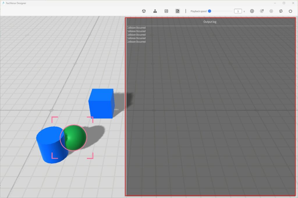
Log Console | Displays debug information output from the Log Record node in the behavior tree. |
Playback Speed | Sets scene playback speed (e.g., 1×, 2×). |
Play / Pause | Start or pause scene playback. |
Step Play | Execute one behavior tree node at a time for step-by-step debugging. |
Continue | Resume execution after a breakpoint until the next breakpoint or the end of the behavior tree. |
Replay | Reset scene state and restart execution. |
Exit | Exit Debug Playback mode and return to editing mode. |
Behavior Tree Breakpoint Debugging
You can set breakpoints on behavior trees to pause execution and check the current state. This helps locate logical errors or issues in condition evaluation.
Steps
- Enter Debug Mode: In the Scene Editor, click Debug Playback .
- Open Behavior Tree Panel: Select a digital twin and click Behavior Tree Preview to view its behavior tree.
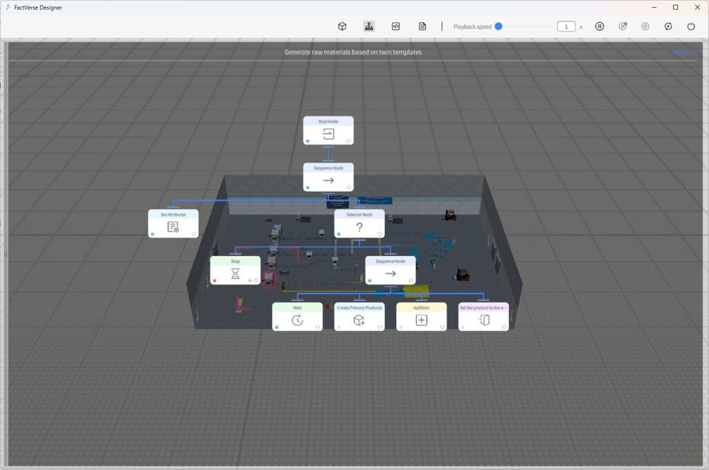
- Check Execution States:
- Blue
 : Node is currently executing
 - Gray
 : Node not yet executed
 - Green
 : Node executed successfully
 - Red
 : Node execution failed
- Blue
- Set Breakpoints: Click the bottom-right corner of a node to add a breakpoint.
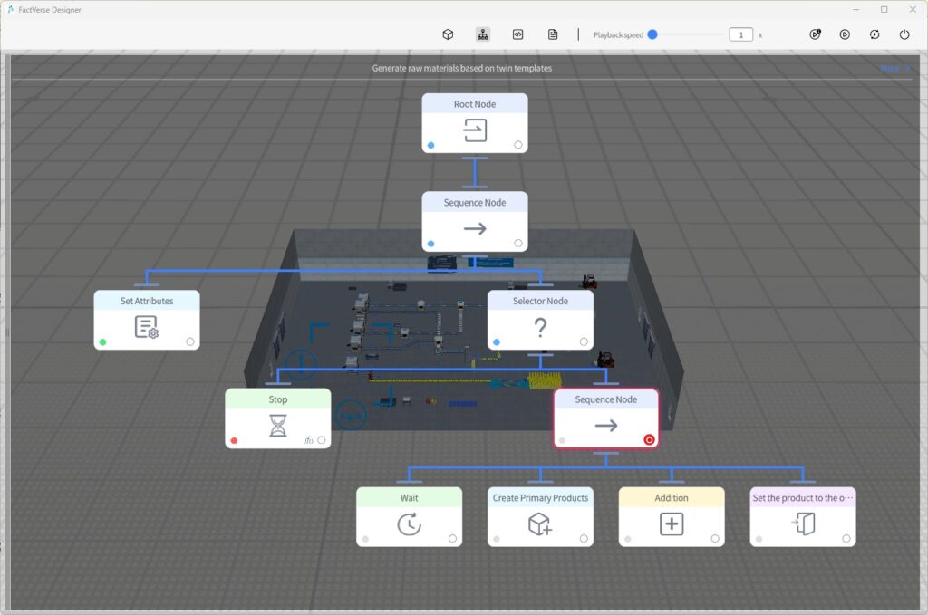
- Debug Behavior Tree:
- Execution pauses when reaching a breakpoint.
- Click the condition icon on the node to open the Condition Panel and check logic evaluation (green = passed, red = failed).
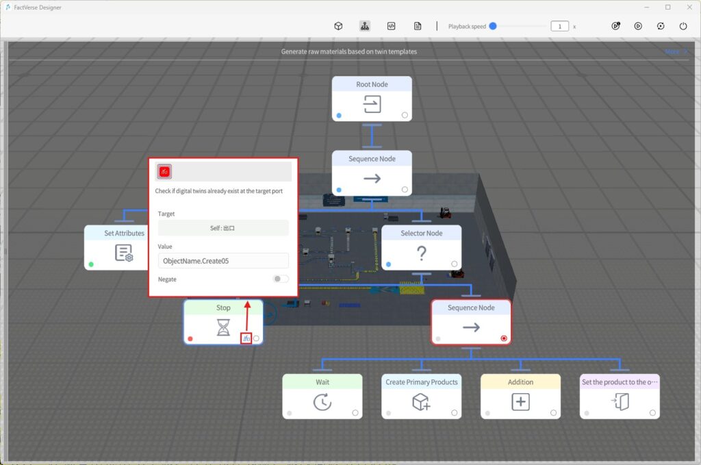
- Control Execution: Use Step Play or Continue from the toolbar to control execution flow.
- Exit Debug Mode: Click Exit to return to editing mode.
- Modify Problem Nodes: Select the digital twin, edit the behavior tree, and re-run debugging to verify the fix.
Simulation Data Debugging
In Debug Playback mode, you can directly modify digital twin attribute values to simulate data changes during runtime. This allows you to observe how behavior trees and scenes respond to input.
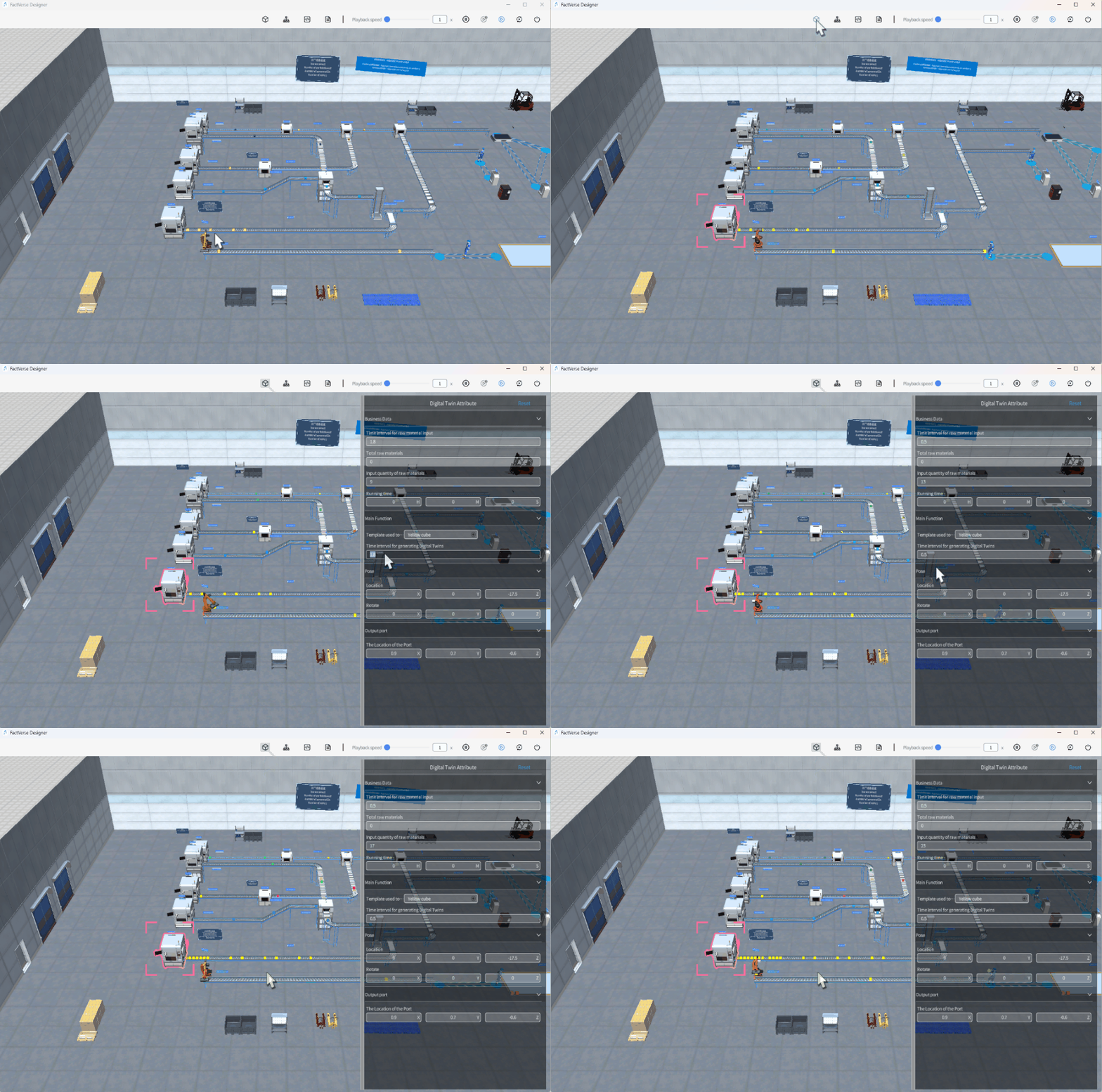
This feature is useful for validating the impact of a single attribute change on digital twin behavior.
Log Output and Issue Tracing
When the Log Record node is used in a behavior tree, the Log Console in Debug Playback mode displays real-time outputs. This helps developers monitor variable states and trace execution processes.

Typical Uses:
- Printing attribute changes
- Recording execution paths
- Checking condition results
