How Can We Help?
Quick start: Build a digital twin scene
This chapter will demonstrate the basic workflow of building a digital twin scene using FactVerse Designer through templates and models from the Virtual Factory DLC. Through the following examples, you will learn about the key steps in creating a digital twin scene.
Basic workflow

Basic steps to set up a digital twin scene:
1. Create digital twin templates: If you use the preset templates available in the Virtual Factory DLC, this step can be skipped. Alternatively, you can create custom digital twin templates by referring to the guidelines in the section on Create digital twin templates.
2. Create digital twins: Generate the required digital twins based on the digital twin templates.
3. Configure scene layout and connection:
a) Arrange the positions and layouts of digital twins, ensuring they collaborate within the scene.
b) Configure connection relationships between digital twins to define the direction of products or logistics.
4. Configure running logic:
a) Configure the attributes of the digital twins to ensure they accurately simulate behaviors in the actual factory.
b) Set up movement paths for the digital twins to ensure they operate and transport along the planned routes.
c) Use the behavior tree editing tool to define the interaction behaviors and actions of the digital twins.
5. Play and review:
a) Run the configured digital twin scene and play it through FactVerse Designer.
b) During playback, check the interaction of digital twins and the layout of the scene to ensure that the simulation meets expectations.
Create digital twins using templates from the Virtual Factory DLC
This section will guide you on how to create the following digital twins using templates from the Virtual Factory DLC:
- A flat roller conveyor
- A source
- An Automated Guided Vehicle (AGV)
- A queue
To create these digital twins using templates from the Virtual Factory DLC, follow these steps:
1. In FactVerse Designer, click on the New Scene button located below the Digital Twin Scene section on the left side of the homepage to open the Scene Editor.

2. Click the Save button ![]() in the toolbar to save the scene. Name the scene as “Simple Scene Demo”.
in the toolbar to save the scene. Name the scene as “Simple Scene Demo”.
3. Create a flat roller conveyor:
a). Click ![]() in the Digital Twin tab of Resources to open the New Digital Twin window.
in the Digital Twin tab of Resources to open the New Digital Twin window.
b). In the New Digital Twin window, fill in the digital twin information.
- Digital Twin Name: “Conveyor 1”
- Digital Twin Template: Choose the flat roller conveyor template from the Virtual Factory DLC, for example: Public Directory/FactVerseDLC/Flat roller conveyor.
- Storage Location: “Private”

4. Create a source:
a). Click ![]() in the Digital Twin tab of the Resources pane to open the New Digital Twin window.
in the Digital Twin tab of the Resources pane to open the New Digital Twin window.
b). In the New Digital Twin window, fill in the following digital twin information:
- Digital Twin Name: “Source 1”
- Digital Twin Template: Choose the source template from the Virtual Factory DLC, for example: “Public Directory/FactVerseDLC/Source.”
- Storage Location: “Private”

5. Create a queue:
a). Click ![]() in the Digital Twin tab of the Resources pane to open the New Digital Twin window.
in the Digital Twin tab of the Resources pane to open the New Digital Twin window.
b). In the New Digital Twin window, fill in the following digital twin information:
- Digital Twin Name: “Queue 1”
- Digital Twin Template: Choose the queue template from the Virtual Factory DLC, for example: Public Directory/FactVerseDLC/Queue.
- Storage Location: “Private”

6. Create an AGV:
a). Click ![]() in the Digital Twin tab of the Resources pane to open the New Digital Twin window.
in the Digital Twin tab of the Resources pane to open the New Digital Twin window.
b). In the New Digital Twin window, fill in the following digital twin information:
- Digital Twin Name: “AGV 1”
- Digital Twin Template: Choose the AGV template from the Virtual Factory DLC, for example: Public Directory/FactVerseDLC/AGV.
- Storage Location: “Private”

7. Drag and drop “Source 1,” “Conveyor 1,” “Queue 1,” and “AGV 1” into the scene.
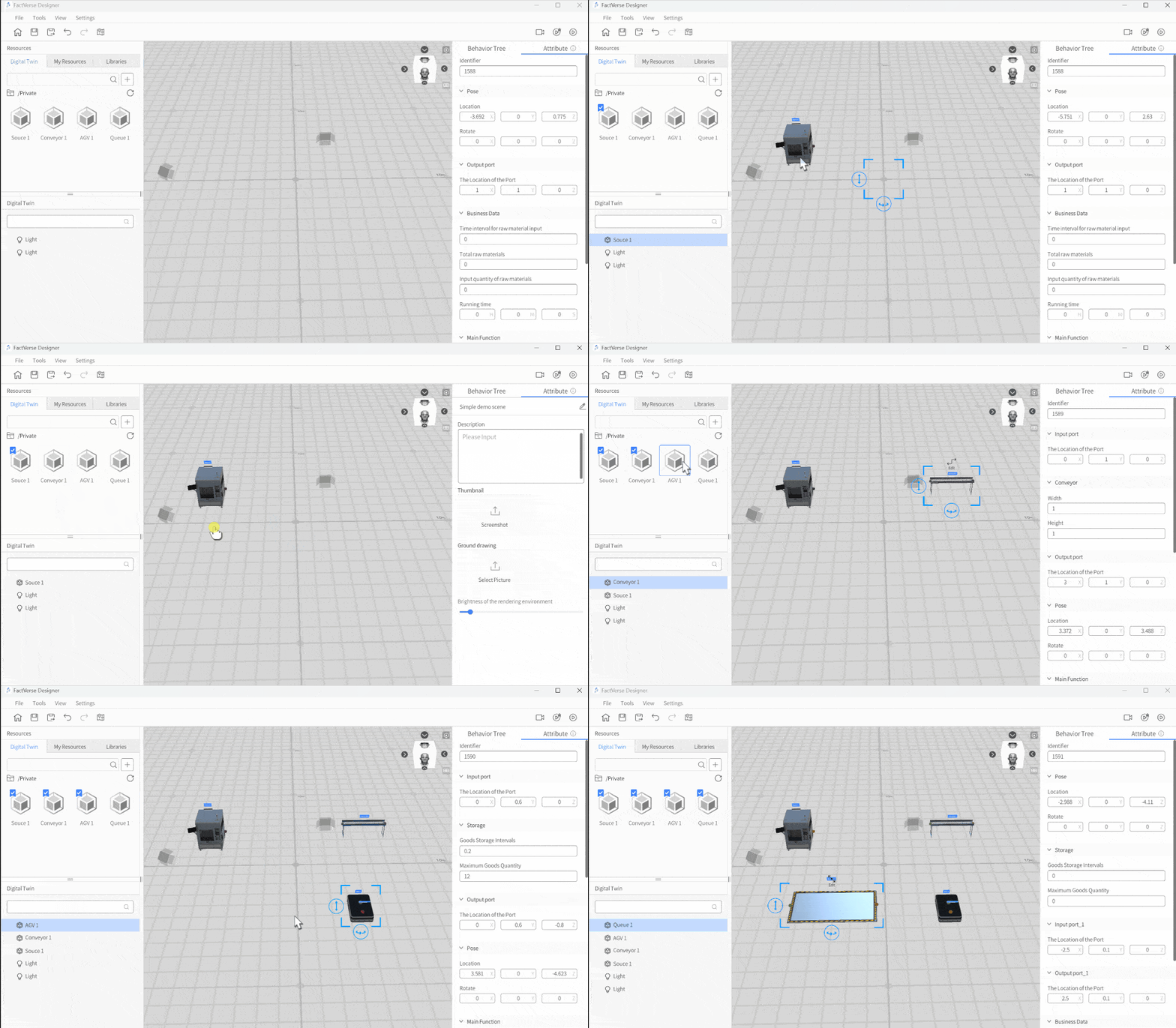
8. Click the Save button ![]() on the Toolbar to save the scene.
on the Toolbar to save the scene.
Configure scene layout and connections
Adjust the length and height of “Conveyor 1”
You can adjust the length and height of the conveyor belt using the conveyor belt editing tool to suit your requirements. Here are the steps to adjust it:
1. In the Scene Area, select “Conveyor 1” and click on Edit.
2. In the editing mode, you can use the conveyor editing tool to stretch the conveyor, adjusting its length, and also modify the conveyor height.
a). Stretching the conveyor: In editing mode, click on one endpoint of the length adjustment line (red) of the conveyor editing tool, then hold down the left mouse button and drag the mouse to adjust the conveyor length.
b). Adjusting conveyor height: In editing mode, click on the height adjustment line (green) endpoint of the conveyor editing tool, then hold down the left mouse button and move the mouse up or down to adjust the conveyor height.
3. Once you finish adjusting, click the End edit button to exit the conveyor editing mode.
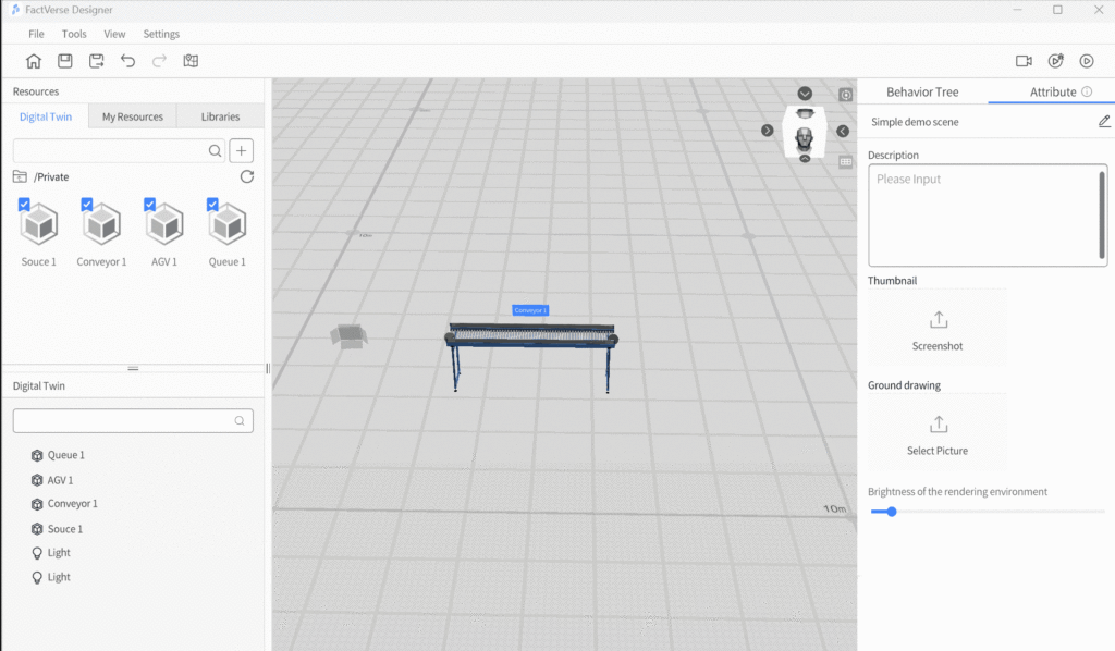
4. Click the save button![]() in the toolbar to save the scene.
in the toolbar to save the scene.
Add a new node to “Conveyor 1”

To add a new node to ” Conveyor 1″, follow these steps:
1. Select “Conveyor 1” and click on the Edit button to enter the editing mode.
2. In the Scene Area, double-click the mouse on a blank space to add a new node to the conveyor. If you need to delete a node, click on the Delete node option to remove the end section of the conveyor.
3. Once you finish adding the node, click the End Edit button to exit the editing mode for the conveyor belt.
4. Click the save button![]() in the toolbar to save the scene.
in the toolbar to save the scene.
Connect the input and output ports of the digital twins
In the virtual factory scene, to enable the transportation of goods between digital twins on the production line, it is necessary to connect the input and output ports of the digital twins.
This section will connect the following input and output ports:
- Output port of “Source 1” (
 ) and input port of “Conveyor 1” (
 )
) - Output port of “Conveyor 1” (
 ) and input port of “AGV 1” (
 )
) - Output port of “AGV 1” (
 ) and input port of “Queue 1” (
 )
)
Note: There is no need to connect the input and output ports of the same digital twin.
Follow the steps below to connect the input and output ports:
1. Click on the output port of “Source 1” (![]() ) in the scene, then click on Connect.
) in the scene, then click on Connect.
2. Move the mouse over the input port of “Conveyor 1” (![]() ) and left click to finish a connection between the output port of “Source 1” (
) and left click to finish a connection between the output port of “Source 1” (![]() ) and the input port of “Conveyor 1” (
) and the input port of “Conveyor 1” (![]() ).
).
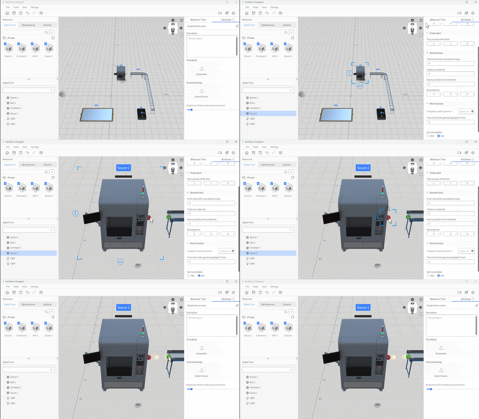
3. Repeat the same process to connect the following input and output ports:
- Output port of “Conveyor 1” (
 ) and input port of “AGV 1” (
 )
) - Output port of “AGV 1” (
 ) and input port of “Queue 1” (
 )
)

4. Click the save button![]() in the toolbar to save the scene.
in the toolbar to save the scene.
Configure running logic
Configure main function of “Source 1”
In this section, we will explain how to set the main function of ” Source 1″ to enable simulation of the production process in your virtual factory scene. Follow these steps to set the main function of ” Source 1″:
1. In the Scene Area, select “Source 1”.
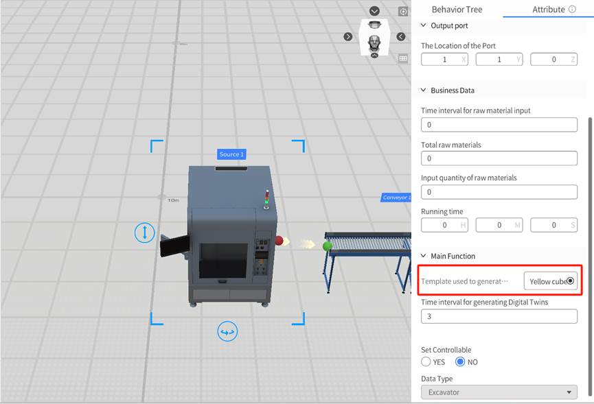
2. In the Attribute Pane, find “Template used to generate digital twins” under the Main Function, and click the select button next to it. In the opened template list, select a product template from the DLC. This way, the source will produce specific items based on this template.
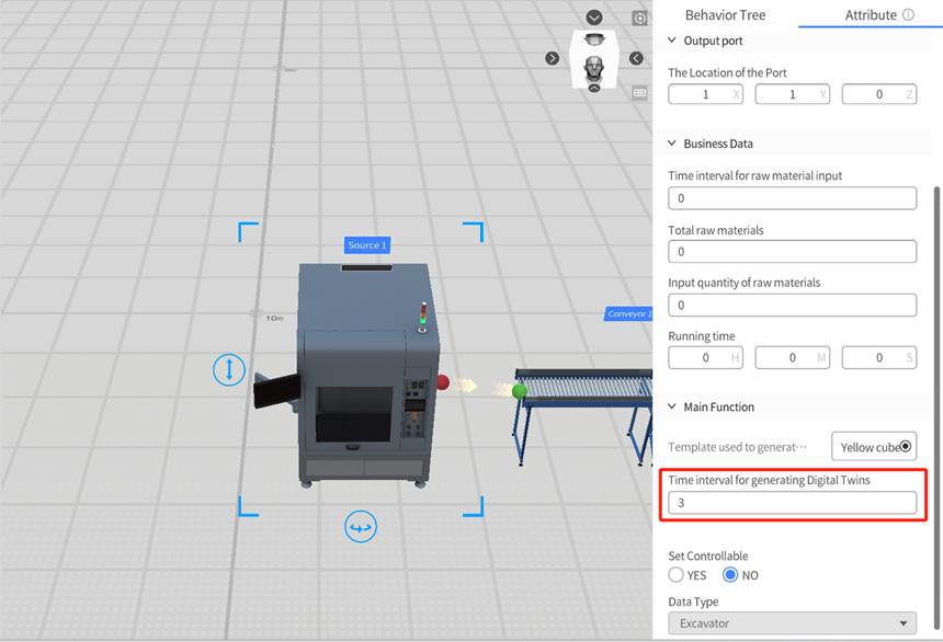
3. In the Attribute Pane, modify the Time interval for generating digital twins for ” Source 1″ (i.e., the time interval for the source to produce items). You can set the time interval to an appropriate value to simulate the production pace in an actual factory.
4. Click the save button ![]() in the toolbar to save the scene.
in the toolbar to save the scene.
Modify the speed of “Conveyor 1”
In this section, we will adjust the speed of “Conveyor 1” to “5” meters per second, allowing the conveyor to operate at a faster pace during the simulation.
1. In the Scene Area, click to select “Conveyor 1.”
2. In the Attribute Pane, modify the value of the Conveyor Speed to “5.”

3. Click the save button![]() in the toolbar to save the scene.
in the toolbar to save the scene.
Create a travel path for “AGV1”
Creating a travel path for “AGV1” allows it to move according to the defined route. Follow these steps to create a travel path for the AGV:
1. Click on the path map button ![]() in the toolbar to open the path planning interface.
in the toolbar to open the path planning interface.
2. Click on the build button ![]() in the toolbar to enter build mode.
in the toolbar to enter build mode.
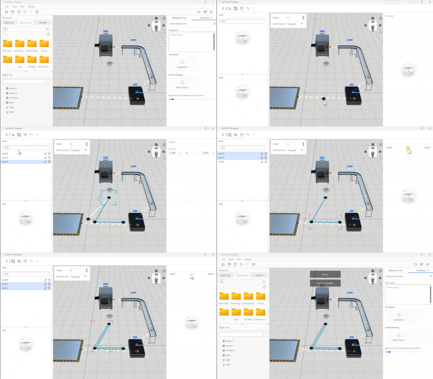
3. Click on three different positions in the Scene Area to create three path points for the AGV:
-
- point0: Pick Up point
- point1: Delivery point
- point2: Charge point
4. Click on the select button ![]() in the toolbar to enter select mode.
in the toolbar to enter select mode.
5. Select the connecting line between point0 and point1 and set the connection direction to bidirectional ↔.
6. Select the connecting line between point1 and point2 and set the connection direction to bidirectional ↔.
7. Click on the < button to exit the path planning interface, return to the Scene Editor interface, and a prompt window to save the path will appear.
8. In the prompt window, click on the YES button to save the path.
9. Click the save button![]() in the toolbar to save the scene.
in the toolbar to save the scene.
Set the main function of “AGV 1”
Setting the main function of “AGV1” ensures that it follows the predefined path and parameters to execute tasks.
Follow these steps to set the main function of “AGV 1”:
1. In the Scene Area, select “AGV 1.”
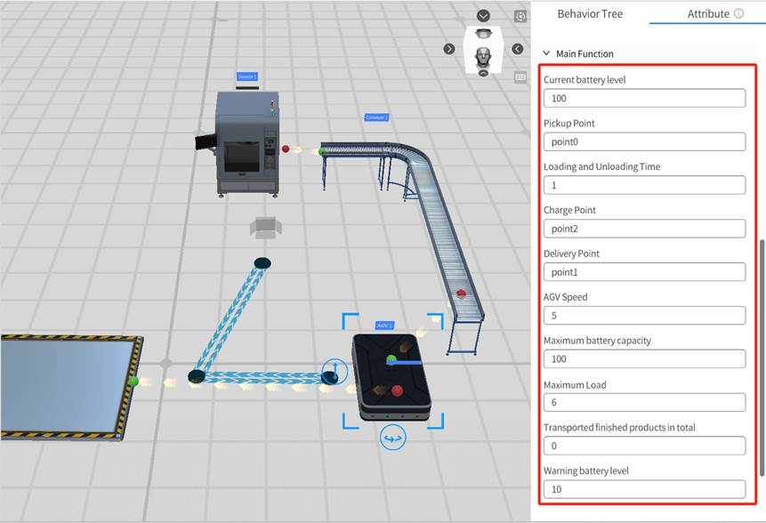
2. Set the moving path of AGV 1.
- Change PickUp Point to the previously set path point name, e.g., point0.
- Change Delivery Point to the previously set path point name, e.g., point1.
- Change Charge Point to the previously set path point name, e.g., point2.
3. Set the AGV speed to “5.”
4. Set the Maximum load to “6” (indicating that it can carry up to 6 items).
5. Loading and Unloading Time to “1” (representing the time taken to load or unload goods, which is 1 second).
6. Click the save button![]() in the toolbar to save the scene.
in the toolbar to save the scene.
Configure the attribute of the queue
Configure the attributes of the queue, including the maximum load of goods and the interval settings for goods storage.

Preview the scene
You can preview the scene and adjust the playback settings by following these steps:
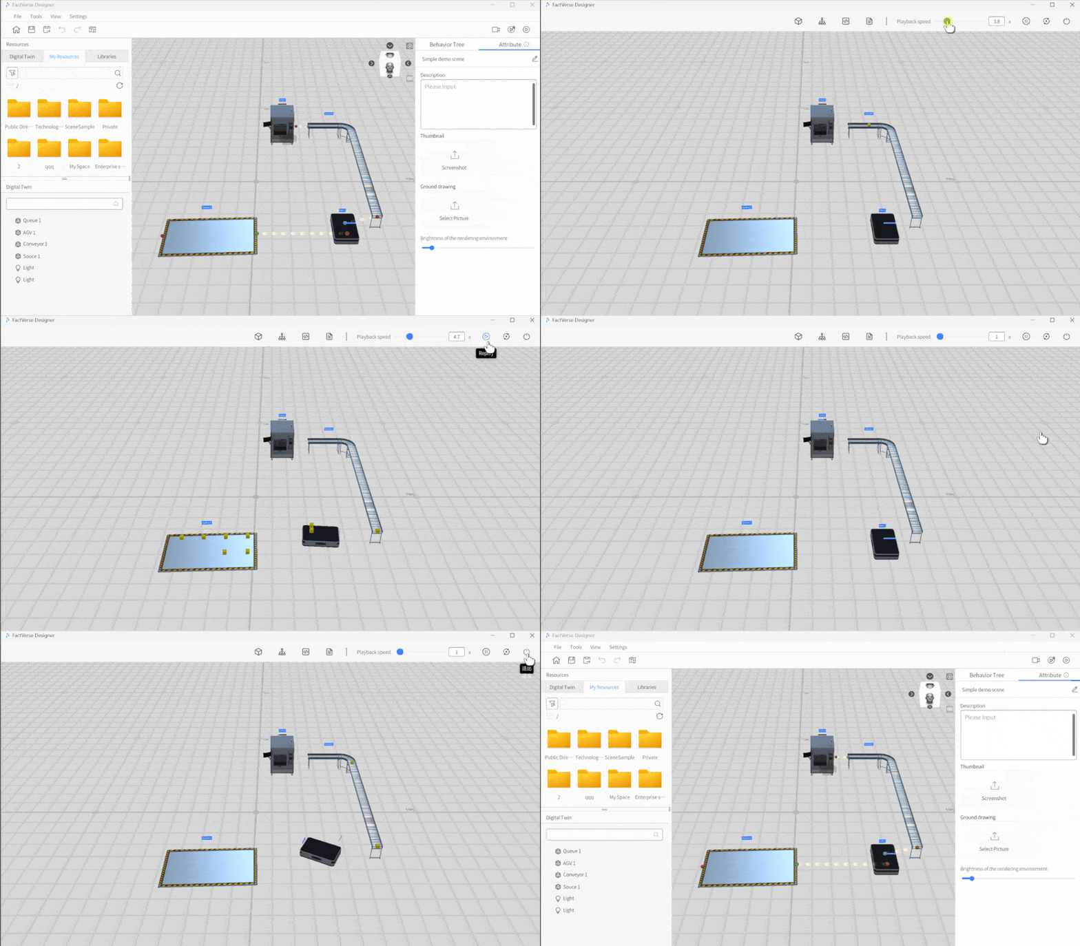
1. Click the Play button ![]() in the Scene Editor toolbar to start previewing the scene to see how the entire scene.
in the Scene Editor toolbar to start previewing the scene to see how the entire scene.
2. During playback, you can use the playback progress bar to control the playback speed. If you need to pause the playback, you can click the pause button.
3. Click the Exit button ![]() to exit playback mode.
to exit playback mode.
