How Can We Help?
Function descriptions
Create digital twin templates
FactVerse Designer provides two methods to create digital twin templates to meet different needs:
Customize a preset template
The Virtual Factory DLC includes a range of common templates, such as sources, conveyors, and AGVs (Automated Guided Vehicles). Users can select these preset templates and customize them to meet their specific needs, making the creation of digital twin templates both straightforward and efficient.
Customize a preset queue template
In this example, we will use the preset Queue template from the Virtual Factory DLC to create a customized queue template that allows users to modify default attribute values. Follow the steps below:
1. Click the Open Template button below the Digital Twin Template on the left side of the homepage to open the template editor.
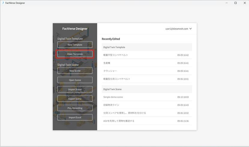
2. In the prompt window, choose the “Queue” template and click the Open button to open the “Queue” template in the Template Editor.

3. Click the Save As button ![]() to open the Save As window.
to open the Save As window.
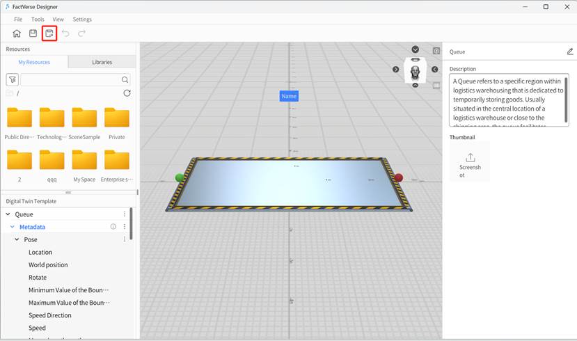
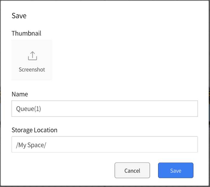
4. In the Save window, choose the storage directory, specify the template name, and then click Confirm to complete the template’s save as process.
5. In the Digital Twin Template pane, select the Width of Goods under the Storage structure. In the Attribute Pane on the right side, change the default value to 0.2.
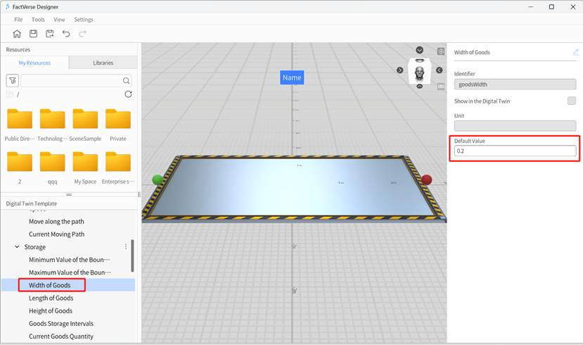
6. Similarly, change the default values for “Goods Length” and “Goods Height” to 0.2.
7. Click the Save button ![]() to save the template.
to save the template.
Create a brand-new source template
Users can create entirely new templates from scratch, fully customized to meet specific scene requirements.
Example: Create a color-changing cube template
This example demonstrates how to change the color of a cube based on its signal value.
1. Create a cube template:
a) Click on New Template on the homepage to open the template editor.
b) Drag the “Cube” from the Libraries into the scene area and position it appropriately.
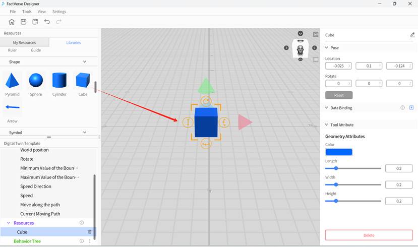
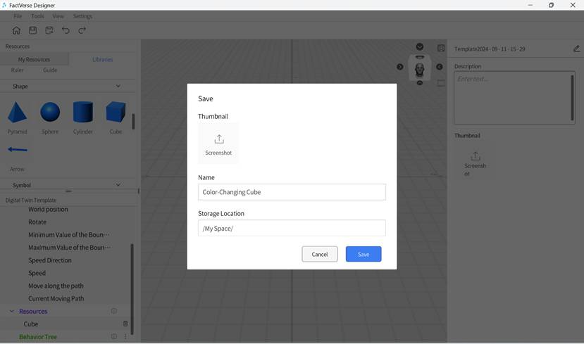
c) Click the save button ![]() on the toolbar and name the template “Color-Changing Cube.”
on the toolbar and name the template “Color-Changing Cube.”
2. Add main function structure:
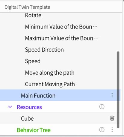
a) In the Digital Twin Template pane, click︙next to Metadata and select Add Structure.
b) Scroll down to find the newly added structure “Part_1,” click on “Part_1,” and rename the structure to “Main Function” in the attributes area.
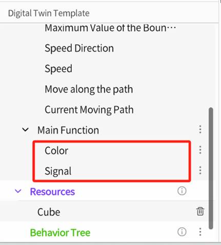
c) Under the “Main Function” structure, add two attributes: Color (Color) and Signal (Int).
3. Bind the color attribute data:
a) In the scene area, select the cube model.
b) In the right-side attributes panel, click the Add button ![]() next to Data Binding, then select the “Color” attribute from the attributes list.
next to Data Binding, then select the “Color” attribute from the attributes list.
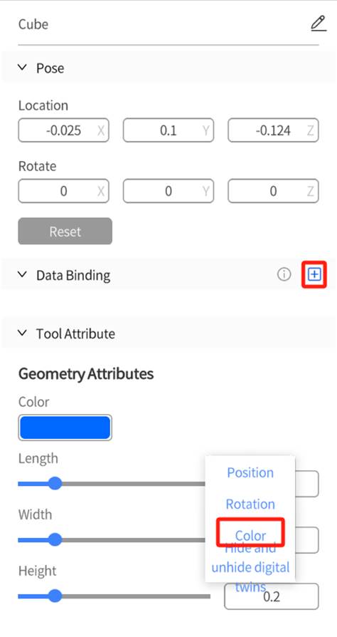
c) In the color attribute binding window, click ![]() and choose the “Color” attribute from the Main Function structure.
and choose the “Color” attribute from the Main Function structure.
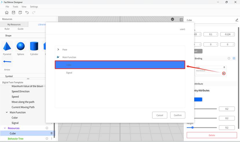
d) Click Confirm to complete the color data binding.
e) Click the save button ![]() on the toolbar to save the template.
on the toolbar to save the template.
4. Create the behavior tree—change color with the signal:
a) In the Digital Twin Template pane, click︙next to the Behavior Tree section and select “Create Behavior Tree.”
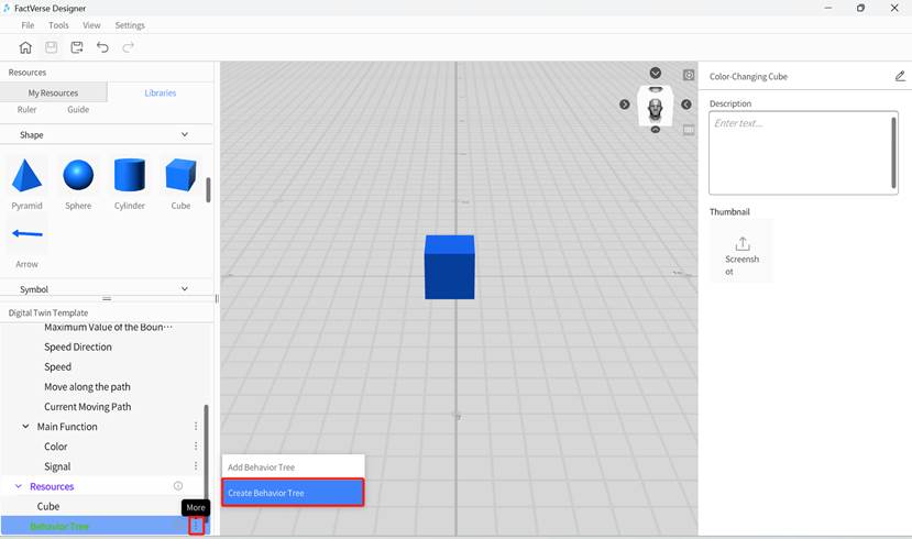
b) Save the behavior tree and name it “Change color with the signal.”
5. Edit behavior tree logic:
a) Double-click the “Change color with the signal” behavior tree to open the behavior tree editor.
b) Add a Selector node under the Root node.
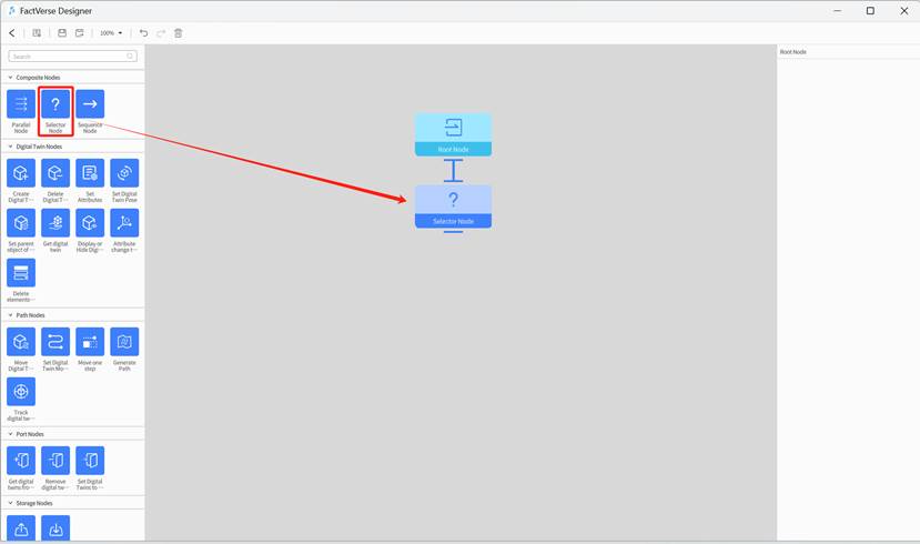
c) Add a Sequence node under the Selector node and set condition to “Compare two digital twin attributes” for the Sequence node.
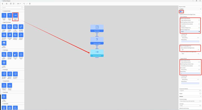
The condition settings for “Compare attributes of two digital twins” are as follows:
- Source attribute
- Method to get attributes: Select attribute directly
- Get location: Attribute of digital twin
- Attribute of digital twin: Select “Color-changing cube” template -> “Signal”
- Way of finding digital twin: self
- Target attribute
- Method to get attributes: Select attribute directly
- Get location: Manual entry
- Manual entry: 1
- Comparison method: Equal to
d) Add a Set Attributes node under the Sequence node and set the node’s attributes.
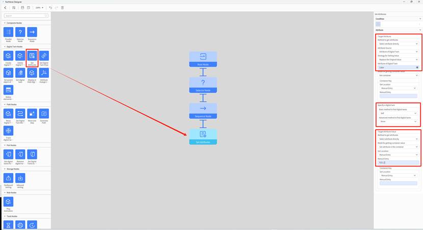
The “Set Attributes” node’s attributes are as follows:
- Target attribute
- Method to get attributes: Select attribute directly
- Attribute source: Attribute of digital twin
- Strategy for setting value: replace the original value
- Attribute of digital twin: Select “Color-changing cube” template -> “Color” attribute
- Specify a digital twin
- Basic method to find digital twins: Self
- Target attribute value
- Method to get attributes: Select attribute directly
- Get location: Manual entry
- Manual entry: 0,0,1,1
Explanation: The logic of “Sequence Node 1” and “Set Attributes 1” determines that when the cube’s “Signal” attribute value is 1, the cube’s color changes to RGBA(0,0,1,1).
e) Add “Sequence node 2”:
i. Copy and paste “Sequence Node 1,” which will automatically be added below the Selector node.
ii. Rename it to “Sequence Node 2.”
iii. Set the manual entry value in the Target attribute to “2.”
f) Add “Set Attributes 2” node under “Sequence Node 2”:
i. Copy and paste “Set Attributes 1” node, which will automatically be added below “Sequence Node 1.”
ii. Rename it to “Set Attributes 2.”
iii. Delete the line connecting “Sequence Node 1” and “Set Attributes 2” nodes, and reconnect “Sequence Node 2” to “Set Attributes 2” node.
iv. Modify the manual entry value of the Target attribute in “Set Attributes 2” node to “0,1,0,1.”
g) Add “Sequence node 3”:
i. Copy and paste “Sequence Node 1,” which will automatically be added below the Selector node.
ii. Rename it to “Sequence Node 3.”
iii. Set the manual entry value in the Target attribute to “3.”
h) Add “Set Attributes 3” node under “Sequence Node 3”:
i. Copy and paste “Set Attributes 1” node, which will automatically be added below “Sequence Node 1.”
ii. Rename it to “Set Attributes 3.”
iii. Delete the line connecting “Sequence Node 1” and “Set Attributes 3” nodes, and reconnect “Sequence Node 3” to “Set Attributes 3” node.
iv. Modify the manual entry value of the Target attribute in “Set Attributes 3” node to “1,0,0,1.”
i) Add “Sequence node 4”:
i. Copy and paste “Sequence Node 1,” which will automatically be added below the Selector node.
ii. Rename it to “Sequence Node 4.”
iii. Set the manual entry value in the Target attribute to “4.”
j) Add “Set Attributes 4” node under “Sequence Node 4”:
i. Copy and paste “Set Attributes 1” node, which will automatically be added below “Sequence Node 1.”
ii. Rename it to “Set Attributes 4.”
iii. Delete the line connecting “Sequence Node 1” and “Set Attributes 4” nodes, and reconnect “Sequence Node 4” to “Set Attributes 4” node.
iv. Modify the manual entry value of the Target attribute in “Set Attributes 3” node to “0,1,1,1.”
The following diagram shows the complete behavior tree structure:
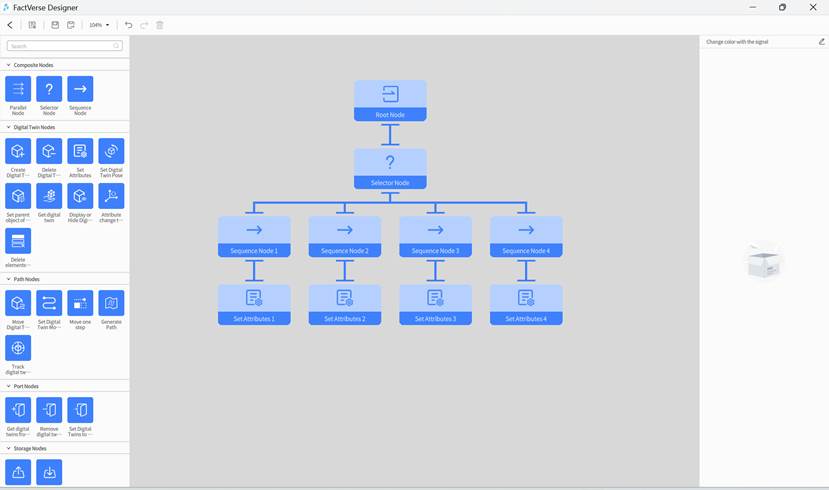
6. Save behavior tree:
a) Click the save button on the toolbar to save the behavior tree.
b) Click < to exit the behavior tree editor.
7. Save template: Click the save button on the toolbar to save the template.
8. Exit template editor: Click the home button to exit the template editor and complete the template editing.
By following these steps, you can create a digital twin template for a color-changing cube. You can use this template to create cubes, set the cube’s “Signal” attribute value, and observe the color changes of the cube.
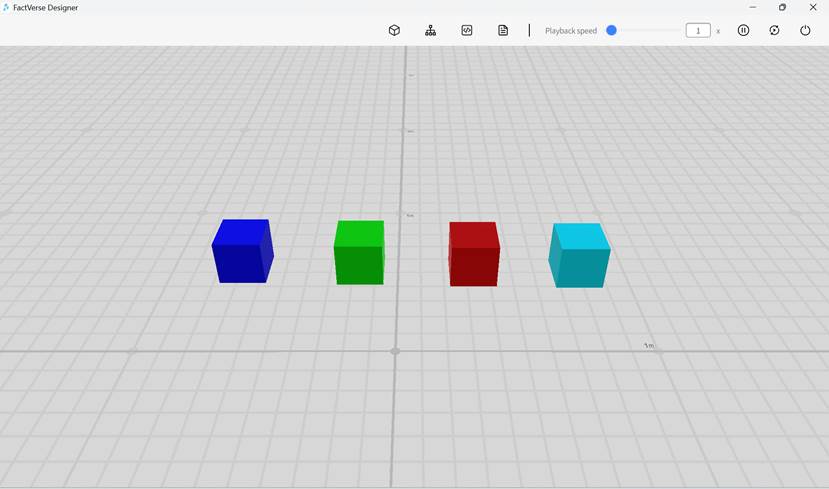
Create digital twins
Users can manage digital twins using templates either by creating them individually or in bulk.
Create a single digital twin
Users can create a single digital twin at a time using a digital twin template.
1. Create a new scene or open an existing one.
2. In the scene editor, click the “Add” button ![]() in the Digital Twin pane of Resources, fill in the digital twin information, and complete the creation.
in the Digital Twin pane of Resources, fill in the digital twin information, and complete the creation.
Example: Create a Source digital twin
This example demonstrates how to use the Source template from the DLC to create a digital twin named “Source 2” and add it to the scene. The following are the specific steps:
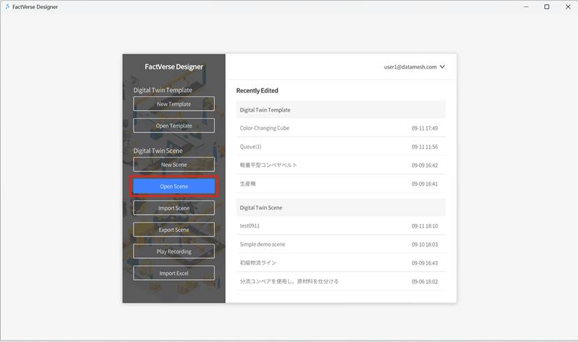
1. Click the Open Scene button on the homepage to open the scene selection window.
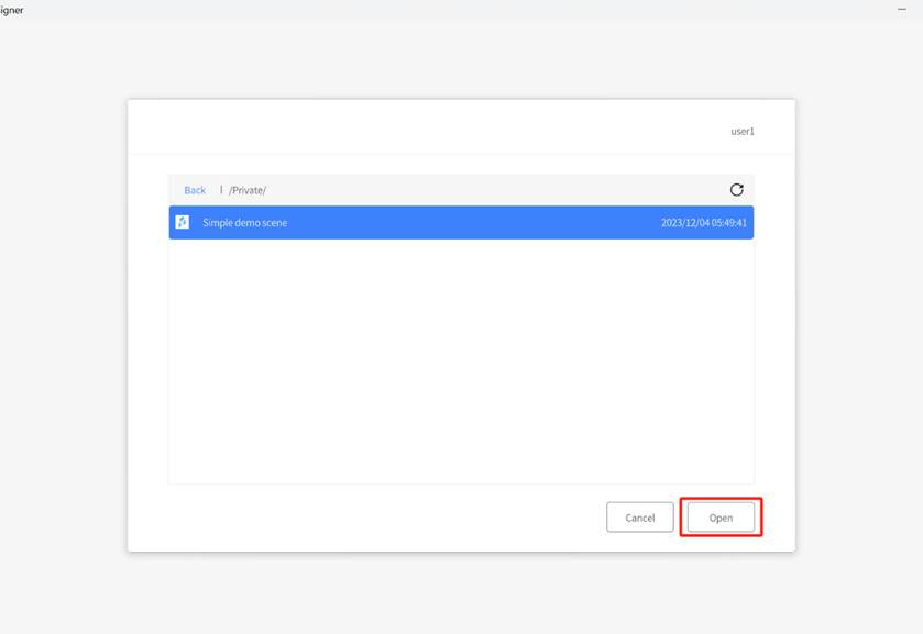
2. Browse the scene directory, select the scene you want to open, and click on it to open the Scene Editor.
3. In the Scene Editor, click the button ![]() in the Digital Twin tab of Resources to open the new digital twin window.
in the Digital Twin tab of Resources to open the new digital twin window.
4. In the new digital twin window, enter the digital twin’s name as “Source 2,” select the digital twin template “Source” from DLC, and set the digital twin’s storage location.

5. Click the Confirm button to complete the creation of Source 2.
6. In the storage directory, find the newly created “Source 2” and drag it into the Scene Area.
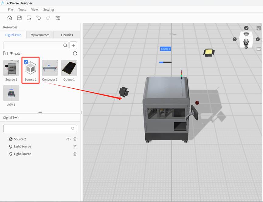
By following these steps, you have successfully created a digital twin named “Source 2” using the source template and added it to the scene. Now, you can proceed with other editing operations, such as setting digital twin attributes and running logic, and more, to build a complete digital twin scene.
Create batch digital twins
Users can create batch digital twins by exporting, filling out, and importing a spreadsheet.
1. Open the digital twin template: On the homepage, click the Open Template button to select and open the digital twin template you will use for batch creation.
2. Export spreadsheet:
a) In the template editor menu, click File > Export as .xlsx file.
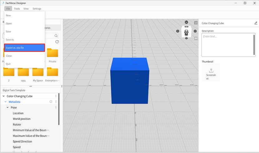
b) In the pop-up window, enter the desired spreadsheet name and storage path, then click Save.
3. Fill out the digital twin Information: Open the saved Excel spreadsheet and fill in the digital twin information. You can choose whether to include each attribute based on actual needs, and follow the example format in the spreadsheet. After editing, save the spreadsheet.

Note: To modify an existing digital twin, you must fill in the digital twin’s ID in the spreadsheet. If you are creating a new digital twin, the digital twin ID in the spreadsheet can be left blank.
4. Import the spreadsheet:
a) Click the homepage button ![]() to return to the homepage.
to return to the homepage.
b) On the homepage, click the Import Excel button.
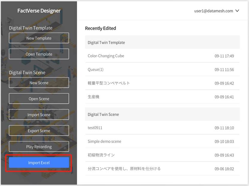
c) Upload the spreadsheet saved in Step 3 to complete the batch creation of digital twins.
Path planning
Path planning constrains the movement trajectory of the digital twin in a digital twin scene. It forms a directed connected graph of movable range by defining a series of key points and their connectivity. Users can specify the movement path on this graph to ensure that the digital twin moves in the scene according to the prescribed route. Path planning is for the entire scene, and different digital twins can share consistent navigation rules.
The feature includes the following main contents:
- Key Points: Key points are marked in the scene and serve as vertices in the connected graph.
- Connectivity: Connectivity defines the relationships between key points, including whether they can be connected and the direction of the connections, forming a directed graph.
- Path: Paths are specified as a series of consecutive vertices in the connected graph, creating a fixed movement route for digital twins.
Construction mode
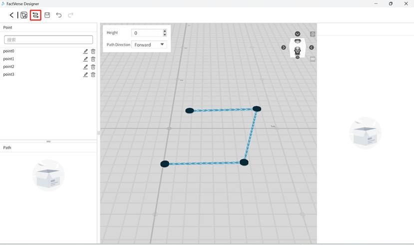
In the construction mode, you can create key points by left clicking on any area in the scene and then move the mouse and click again to create the next key point. The two key points will be automatically connected with the default direction.
To improve the efficiency of path construction, you can configure the default construction settings in the upper left corner of the scene, including the point height and path direction. Created points will apply the default settings.
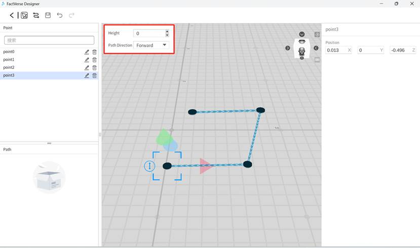
- Height: In construction mode, you can set the point’s height.
- Path Direction: In construction mode, you can set the direction that a point connected to the next one. The direction option includes forward, reverse and bidirectional.
As points are constructed in the scene, corresponding entries will appear in the left-side point list pane, following the naming rule “Point+Num” by default.
After creating the key points, you can perform the following operations:
- Rename or delete points.
- When a point is selected, you can precisely adjust its position data through the coordinate input box in the right-side properties pane.
- When the line connecting two key points is selected, clicking the direction arrow options in the right-side attribute pane can switch the connection direction between the two points.
Selection mode

In the selection mode, you can drag the scene to move the entire view and also select key points to modify their positions.

Basic process of creating paths
1. In the scene editing interface, click the path map button ![]() in the toolbar to enter the Path Planning interface.
in the toolbar to enter the Path Planning interface.
2. Once in the Path Planning interface, use the construction mode to create points. Points will be created on the plane based on the default construction height (0).
3. The newly created points are connected in the default direction, i.e., forward from the current point to the next one.
4. In selection mode, click on points and lines to modify their positions and connection directions.

Import scene and export scene
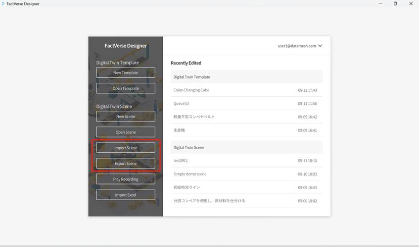
The digital twin scene file (.digpkg file) contains digital twins and other digital twin content in the scene, such as metadata, behavior trees, resources, scene paths, etc. of digital twin templates. Users can choose to import and export digital twin scenes on the homepage.
Business data dashboard
The Business data dashboard can be used to display real-time IoT data and simulated data. Users can select data in the attribute pane, and set the background, text color, font size, and data prefix.
The following are the general steps to bind simulated data:
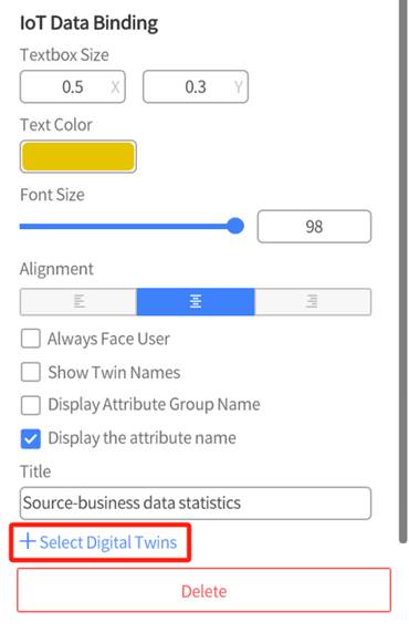
1. Drag the Business data dashboard tool into the scene.
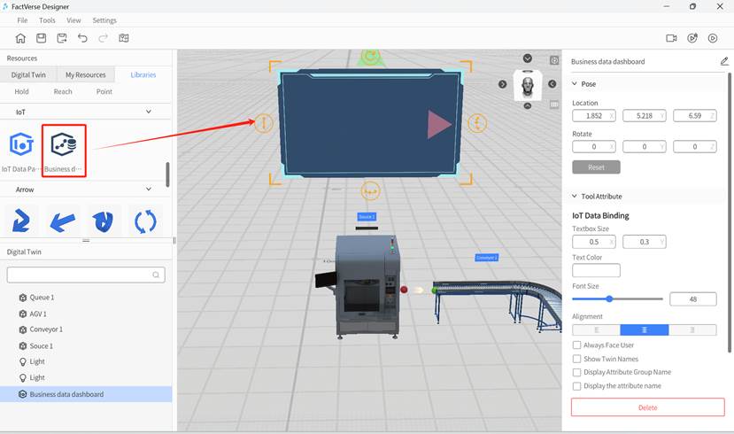
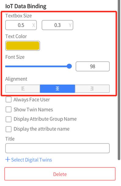
2. Select the business data dashboard, and configure its font size, text color and alignment in the attribute pane.
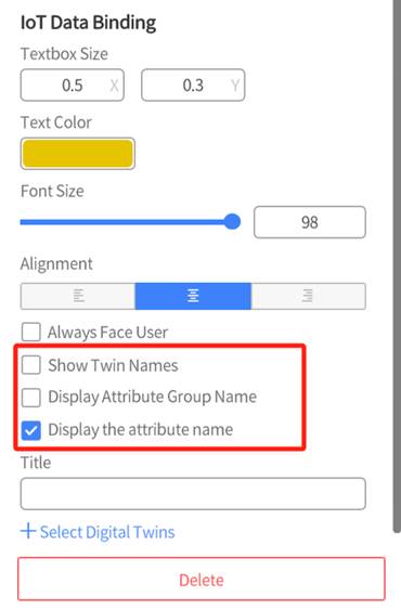
3. Choose the content to display, such as the attribute names of digital twins.
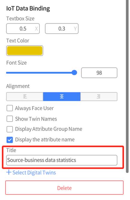
4. Set the title of the dashboard.
5. Click on +Select Twins.
6. After clicking + Select Twins, a list of digital twins in the scene will appear. You can search for digital twins by name. In the list of selected digital twins, find the digital twin you want to bind and click to select it.
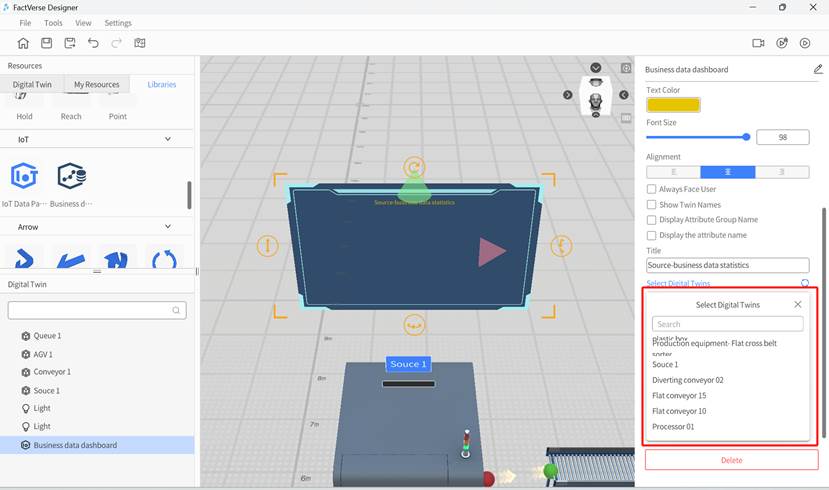
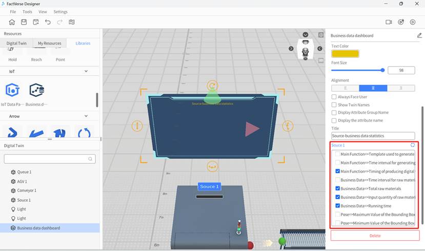
After selecting a digital twin, the original + Select Digital Twin button will display the name of the chosen digital twin. Clicking on this name will bring up the list of digital twins for reselection.
7. After selecting a digital twin, the attributes of the digital twin will be displayed below the digital twin ‘s name. Click to select the attribute data you want to display.
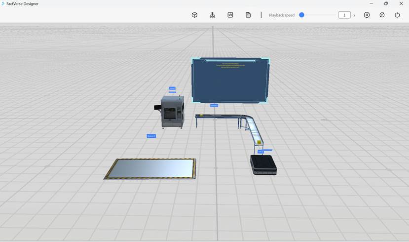
8. Click the play button ![]() in the upper right corner of the page to preview the effect.
in the upper right corner of the page to preview the effect.
Adjust scene perspective
In FactVerse Designer, you can adjust the scene perspective in various ways to better observe and edit the scene. Here are some commonly used methods for adjusting the scene perspective:

- Rotate View: Hold the right mouse button to drag the entire view. The mouse cursor will change to a magnifying glass, allowing the user to observe the model from all angles.
- Adjust Baseline Height: Use Shift + Left mouse button to quickly adjust the baseline height.
- Zoom space: You can zoom in and out by scrolling the mouse wheel. Scrolling up will zoom in, and scrolling down will zoom out.
- Drag Scene: You can drag the scene by holding down the mouse wheel or clicking the scene area and hold the left mouse button to drag the entire scene. This allows you to move the scene horizontally or vertically for better viewing.
Change scene rendering environment
The rendering environment of a scene refers to the lighting effects set in the virtual scene, simulating the propagation, reflection, and refraction of light in the scene. It can affect the appearance, lighting, and shadow effects of objects, enhancing the realism and authenticity of the scene.
In FactVerse Designer, newly created scenes do not have specific rendering effects by default. You can choose from the system’s provided preset rendering environments or customize the rendering environment for your scene to make the virtual environment more realistic and immersive.
To modify the rendering environment of a scene, you can follow these steps:
1. Click on the Settings menu and select Change rendering environment from the dropdown menu. You can open the Change rendering environment window.
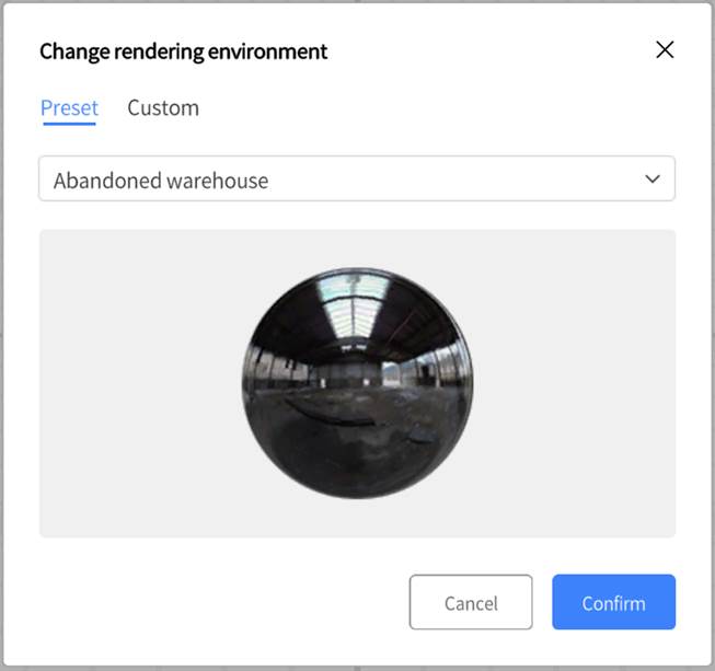
2. You can choose a preset rendering environment. When choosing “None”, the scene will have no specific environmental reflection effects.
You can also create a custom rendering environment to suit the scene’s background and sky effects for different scene requirements and creative purposes.
Steps for custom reflection environment:
1. Prepare six images: These images should correspond to the front, back, left, right, top, and bottom directions of the rendering environment. The images should be in PNG format and follow English naming conventions (Front, Back, Left, Right, Top, Bottom).
2. Compress these images into a zip file and change its extension to .dmcm.
3. Upload this .dmcm file to the resource library on the DataMesh FactVerse platform.
4. In FactVerse Designer, click on the Settings menu and select Change rendering environment from the dropdown menu to open the Change rendering environment window.
5. In the Change rendering environment window, select the Custom tab and click Select rendering environment.

6. In the window for Select rendering environment, find the uploaded .dmcm file.
7. After selecting the file, click the Confirm button to complete the customization of the scene’s rendering environment.
Play recording
The Scene Recording Playback function allows users to conduct horizontal comparison between scenes by contrasting different parameter configurations, layouts, or elements, or by comparing differences between multiple scenes.
Process for scene recording playback
1. Scene recording:
a) In FactVerse Designer, open the scene to be recorded.
b) Click on the Record button ![]() in the toolbar.
in the toolbar.
c) In the Record window, fill in the recording name, duration, and select storage location, then click Confirm.
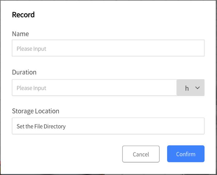
d) Wait until the recording progress reaches 100%, then click Confirm to complete the recording. The recording file contains scene content data and runtime data, which is for playback only and cannot be edited.

e) Click the homepage button ![]() to go back to the homepage.
to go back to the homepage.
f) In the pop-up window, click Save.
2. Play:
a) Click the Play Recording button on the homepage.

b) In the opened window, select the recording file, then click Open.

c) Use the toolbar in the playback interface to play or pause, control playback progress, adjust playback speed, or exit operations.

Behavior tree debugging with breakpoint
You can pause the behavior tree traversal and scene execution by setting breakpoints in the behavior tree. This allows you to view the execution status and condition details of each behavior tree node at that moment, helping you check and debug the behavior tree logic.
1. Enter debug mode
a) Click the breakpoint debugging button ![]() on the toolbar.
on the toolbar.
b) Enter the behavior tree debugging mode. The toolbar will display four playback control buttons:
-
- Play one node: Execute each behavior tree node step by step.
- Resume playing: Continue executing the behavior tree until the next breakpoint or end.
- Replay: Replay the scene.
- Exit: Exit debug mode and return to normal mode.

2. Add a behavior tree breakpoint
a) Select a digital twin: Click on the digital twin to select it.
b) Open the behavior tree panel: Click the behavior tree panel button ![]() on the toolbar.
on the toolbar.
c) Add a breakpoint: In the behavior tree panel, select the node you want to debug and click on the top right corner of the node to add a breakpoint (marked with a red dot).

3. Debug the behavior tree
a) When the behavior tree is running, execution will pause at breakpoints. You can click the condition button ![]() on the top right corner of the node to open the condition panel for that node and view the current execution status and condition details. Conditions that pass are shown in green, while those that do not pass are shown in red.
on the top right corner of the node to open the condition panel for that node and view the current execution status and condition details. Conditions that pass are shown in green, while those that do not pass are shown in red.
b) Use the control buttons on the toolbar for step-by-step execution or to continue playback to check the behavior tree logic and execution.
4. Exit debug mode
a) Click the exit button ![]() on the toolbar to leave debug mode and return to the scene editing interface.
on the toolbar to leave debug mode and return to the scene editing interface.
5. Modify problematic nodes
a) In the scene editor, select the digital twin, open its behavior tree, find the problematic node, and make modifications.
b) After making the necessary changes, run the debug mode again to ensure the issue is resolved.