How Can We Help?
Actions
Actions are the basis of scenario expression and interactive capability.
Actions are the basis of scenario expression and interactive capability. After selecting an element, click the ![]() button in the upper right corner of the attributes pane. An action menu for adding actions will appear. Clicking the action option in the menu to add the corresponding action to the element. Depending on the type of the element and its current state, the available action options may vary.
button in the upper right corner of the attributes pane. An action menu for adding actions will appear. Clicking the action option in the menu to add the corresponding action to the element. Depending on the type of the element and its current state, the available action options may vary.

For models, typically you can add the following six types of actions:
-
- Movement: Effects that alter the position, rotation, and size of the model or sub-elements.
- Disassemble: Action effects that disassemble or spread sub-elements within the model.
- Section cut: Create a section cut effect on the model to show its internal structure.
- Disappear: Create an effect that makes the model disappear.
- Link: Link the model to another scene. Jump to the target scene by clicking the model.
- Change color: Effects that change the color of the model or sub-elements.
If the model comes with built-in animations, you can also configure animation options. For attachment elements and tools, you can only add pose adjustments, disappear actions, and link actions.
Action Sequence: Multiple actions can be added to an element in the same scene, and clicking on a bar in the action list provides easy access to them.

Appear
Appear is the initial configuration option of all elements, allowing you to define the position, rotation, and scale of an element when it appears in the scene, as well as the duration of the appearance.
When you add an element to the scene, you can drag and rotate it to adjust its position and rotation. Additionally, you can make precise parameter adjustments to the Appear action properties of the element to further customize its appearance.

-
- You can use the Position and Rotation settings to adjust the initial pose of an element. The Position setting determines the location of the element’s center in the scene’s coordinate system. For more information on position coordinates, please refer to How to understand 3D coordinates in the scene.
- Reset All: The Reset All button allows you to restore the positions of all child objects of the model relative to the parent object.
- Scale: The Scale setting is used to adjust the size of the model in the scene. You can still modify this configuration by using pose adjustment action in subsequent scenes.
- Appear type: The default Appear type setting is Zoom, which means that the model will appear by gradually scaling up from the center point during playback. If set to Left or Right, the model will move a short distance in the corresponding direction and then stop at the designated appearance position.
- Duration: The default duration is 1 second, which represents the length of time it takes for the Appear action to complete, from the start to the end.
Movement
The Movement action can make the elements in the scene move along a straight or curved path, and change their position, rotation angle, and size through operations such as moving, rotating, and scaling. By adding movement actions, you can create various dynamic effects for elements, such as acceleration, deceleration, or uniform motion.
How to move an element in a straight path
The Movement action enables an element to move along a straight path.

Here are the steps to add and set the Movement action for an element to move along a straight path:
-
- Select the element you would like to move during the scene.
- Click the button
 next to the element’s name in the attributes pane and select the Movement option from the drop-down menu.
 - Move the element in the workspace to change its position or fine-tune the movement parameters in the attribute area, and then set the Duration of the movement action.
- By selecting the Movement Type, set the speed of the movement action.
-
-
- Uniform: The role’s movement speed remains constant throughout the motion.
- Accelerate: The movement gradually accelerates to full speed.
- Decelerate: The movement gradually decelerates from full speed.
- Organic: The movement accelerates to full speed, maintains the speed, and then decelerates to rest.
-
How to move an element in a curved path
You can also use the Movement action to make an element move along a curved path.

Here are some of the attributes that you will need to know to move an element in a curved path.
-
- Curved Path: This option is disabled by default. Enabling this option allows the role’s path to curve around control points.
- Face the Path: When this option is enabled, the element will always face the direction that it is moving.
- Control Point: These are points along the element’s path that guide the way that the path curves. You can set as many as you want, and setting multiple points along one curve allows for more gradual and smoother movements.
The following are steps to add and configure elements to move along a curved path in the movement action:
-
- Select the element you would like to move in the scene.
- Click the button
 next to the element name and select Movement.
 - Check the Curved Path option.
- Adjust model position, rotation, and scale and click Create a control point at the current position.
- Repeat Step 4 to create other control points for the curved path.
- Adjust the position and curvature of the control point to make the curved path smoother.
- Configure Duration and Movement Type of the movement.
- Click the Play button to preview the effect of the movement action.
- Fine-tune the settings of the movement action for the curved path as needed.
Animation
Some models come with their own predefined animations, which can be configured in the Action. When a model contains animations, we can configure the animation of the model in DataMesh Studio, such as setting the playback mode and duration of the animation.
Here are the steps to configure the animation of a model:
1. Select the model in the Elements pane.
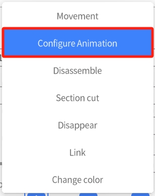
2. Click the button ![]() in the attributes pane and select the Configure Animation option.
in the attributes pane and select the Configure Animation option.
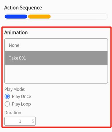
3. In the attributes pane, you can see all the animation names that the model contains.
4. You can select the animation you want to configure, set its playback mode to Play Once or Play Loop, and modify the Duration of the animation.
Disassemble
You can add a Disassemble action to any element that contains sub-elements. By default, the Disassemble action will expand all primary sub-elements under the element. You can set the disassemble effect for all sub-elements in a Disassemble action, or you can continue to add Disassemble actions for sub-elements that contain lower-level sub-elements, thereby achieving an outward-to-inward sequential expansion effect.
Add a Scatter action
To add a Disassemble action for a selected element or sub-element, click the button ![]() next to the element name in the attributes pane. Then, in the action menu, select Disassemble. This will add a Disassemble action to the element or sub-element.
next to the element name in the attributes pane. Then, in the action menu, select Disassemble. This will add a Disassemble action to the element or sub-element.
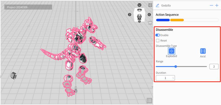
In the Disassemble attributes pane, you can choose between two types of disassembly effects: Exploded and Axial.
-
- Exploded: This option separates sub-elements by pushing them outwards from the center of the parent element. By adjusting the Distance slider or value, you can modify the distance of the sub-element from the parent element.
- Axial: This option arranges sub-elements in a straight line along an axis. By adjusting the Distance slider or value, you can change the spacing of elements in the line. The Direction option refers to the direction in which the sub-elements are arranged.
Exercise 1
To achieve the Disassemble configuration for a monster model and one of its arms within a Disassemble action, you can follow these steps:
1. Select the monster model in the scene.
2. In the attributes pane, click the button ![]() next to the name of the monster model, and select Disassemble in the action menu.
next to the name of the monster model, and select Disassemble in the action menu.
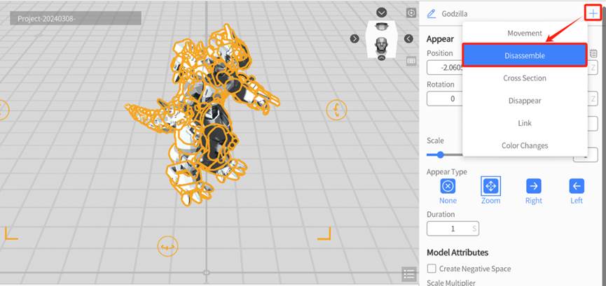
3. Configure Disassemble Type, Range or Distance and Duration.
4. In the workspace, click to select the right arm of the monster model.
5. In the attributes area, Enable the Disassemble action for the arm, and set Disassemble Type, Range or Distance and Duration.
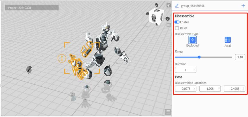
6. Select the monster model again in the workspace, you can see there is only one Disassemble action in the action list.
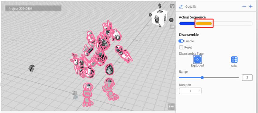
Exercise 2
To add a separate Disassemble action to the right arm of the monster model, you can follow these steps:
1. Select the monster model in the scene.
2. In the attributes pane, click the button ![]() next to the name of the monster model, and select Disassemble in the action menu.
next to the name of the monster model, and select Disassemble in the action menu.
3. Configure Disassemble Type, Range or Distance and Duration.
4. In the workspace, click to select the right arm of the monster model.
5. In the attributes pane, click the button ![]() and select Disassemble in the action menu.
and select Disassemble in the action menu.
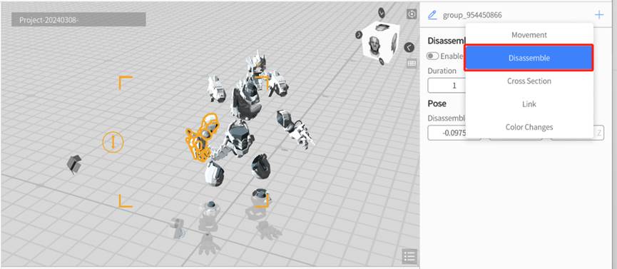
6. Configure Disassemble Type, Range or Distance and Duration.
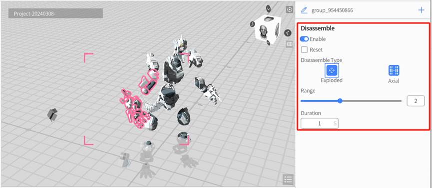
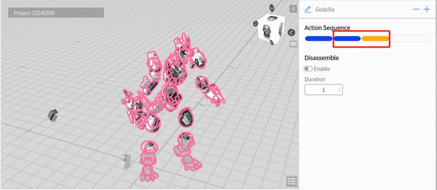
7. Reselect the monster model in the workspace, and you will notice that the action list in the attributes area now displays two disassemble actions. The first disassemble action pertains to the Disassemble action effect of the entire monster model, while the second disassemble action specifically applies to the arm.
Reassemble
Reassembling means removing the Disassemble effect that has been applied to the model, thereby restoring it to its original state.
You can follow these steps to remove the Disassemble action:
1. Select the disassembled model in the workspace.
2. In the attributes pane, click the button ![]() next to the model’s name and select Disassemble in the action menu.
next to the model’s name and select Disassemble in the action menu.
3. Check the Reset option.
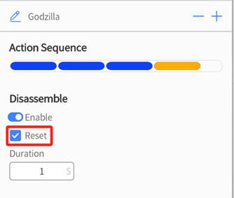
4. This will cause all the previously separated sub-elements to merge together to form the original model.
Cross Section
This action allows you to show the interior of a model by ‘cutting’ into it, which is an effective way to show how a model’s physical counterpart might function. You can adjust which part of the model is removed, how long the cut animation takes, and which direction the cut is made in.
Add a section cut action
To add a section cut to a model, follow these steps:
1. Select the model that you want to add a section cut to.
2. Click the button ![]() near the element’s name in the attributes pane and select the Section Cut option.
near the element’s name in the attributes pane and select the Section Cut option.
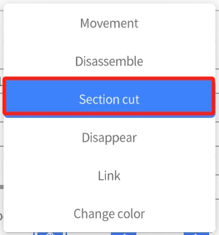
3. The Removal Cube will appear in the workspace, which is a transparent blue cube with three lines that represent each axis. This cube allows you to choose the section of the model that you want to remove. You can drag and rotate the Removal Cube in order to customize your desired cross section, and its position can change whether the model is cut in half, or if a corner is removed.

4. Configure the section in the attributes pane.
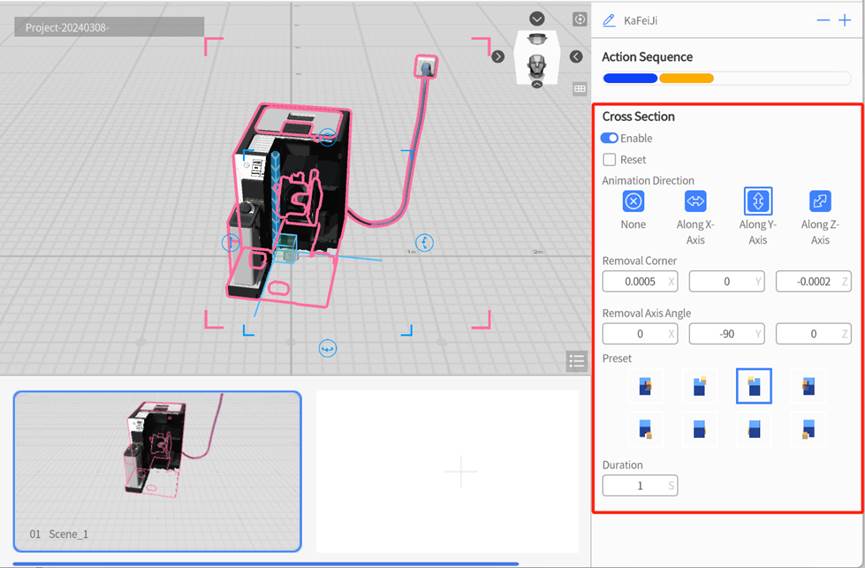
You can configure cross section action as follows:
-
- Animation Direction: The section animation consists of your chosen section fading out in an axis relative to the Removal Cube. This option allows you to choose which axis the fade occurs in.
- Removal Corner: The position of the point where the three faces of the section body intersect. This shows you the point where all three of the Removal Cube’s axes meet. You can also manually input the point’s coordinates for extra precision.
- Removal Axis Angle: Each field represents the angle of one axis of the removal cube. You can manually input the angle in order to change which direction the removal cube is facing.
- Preset: We provide a variety of presets that you might find helpful when choosing your cross section. Each preset has a corner of the model removed, along with a visual guide to help you choose the right one for you. In the visual guides, the blue cube represents your model, and the yellow cube represents the removed section. In addition, the visual guides rotate along with your perspective of the model in the workspace.
5. Click the Preview button to check the section action effect and adjust it according to the effect.
When cross sectioning an element, the default behavior is that all of its sub-elements inherit the cross-section effect. If you would like a specific sub-element to not be affected, follow these instructions below.
1. Select the sub-element that you would like to be exempt from the cross sections effect.

2. In the cross-section settings, toggle the Enable option so that it is active, select the Reset checkbox, and make sure the Animation Direction is set to None.
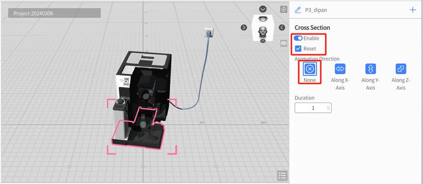
Repair a cross section
After cross-sectioning a model, you may want to reverse the process afterwards. You can simply remove the cross-section action, which will cause the model to suddenly be full again during the next scene, or you can repair it using the same animation for consistency. Here are the steps to do so.
1. Select the cross sectioned element that you want to repair.
2. Click the button ![]() next to the element’s name in the attributes pane and select Section cut from the action menu.
next to the element’s name in the attributes pane and select Section cut from the action menu.
3. In the Section cut settings in the attributes pane, make sure that the Reset checkbox is checked.
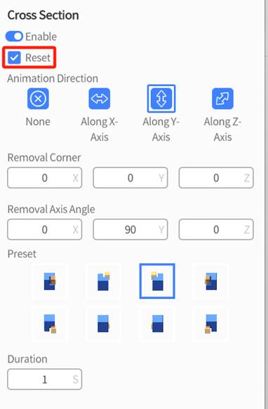
4. Configure the Section action through the settings of Animation Direction, Removal Corner, Removal Axis Angle, Preset and Duration.
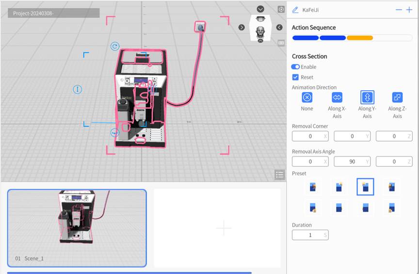
5. Click the play button to preview the effect of removing the section and make section adjustments as needed.
Link
When previewing a scenario or playing it in DataMesh One, you can easily navigate to the target scene by clicking on a model or sub-object that has a Link action associated with it.
Note: If the target scene is deleted, the link will become inactive. In addition, links are only active during the scene that they first appear in. To add another link to the model in a different scene, you must first remove the original link, then add the new link.
To add a Link action to a model or sub-object, follow these steps:
1. Select the element you would like to attach a link to.
2. Click the button ![]() next to the element’s name in the attributes pane and select the Link option.
next to the element’s name in the attributes pane and select the Link option.

3. In the Link Settings in the attributes pane, make sure the Disable option is unchecked, and then select the scene you would like the model to be able to jump to using the Link Scene option.
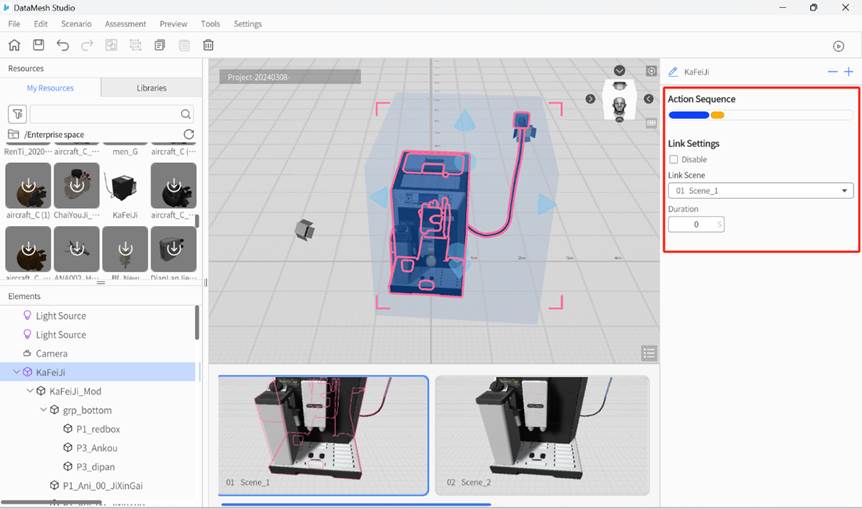
4. Once linked, the role will have a glowing blue box that signifies the link’s area. You can drag the surrounding blue cones in order to move this link area to your liking.

Disappear
This action allows you to remove an element during any scene after the scene where it was first placed.
The steps to add a Disappear action to an element are as follows:
1. Select the role that you would like to disappear.
2. Click the button ![]() next to the element’s name in the attributes pane and select the Disappear option.
next to the element’s name in the attributes pane and select the Disappear option.
3. In the Disappear settings in the attributes pane, select your preferred type. The Disappear type shrinks the element into its own center until it disappears and Left or Right makes the element move a short distance in the corresponding direction before vanishing.

Change color
The Change Color action is an animation effect that enables an element to change colors during the animation. It can be applied to any node of a model, whether it is the entire model or specific sub-objects. When you add the Change Color action to the entire model, the color changes will be applied to the currently selected model and all its sub-objects, allowing for dynamic and visually appealing color transformations.
Here are the steps to add a Change Color action:
1. Select the element that you want to change color during the scene.
2. Click the button ![]() next to the element’s name in the attributes pane and make sure that the Change Color action is enabled.
next to the element’s name in the attributes pane and make sure that the Change Color action is enabled.
3. Then, set the color you would like the element to change to, the transform type, and the duration.
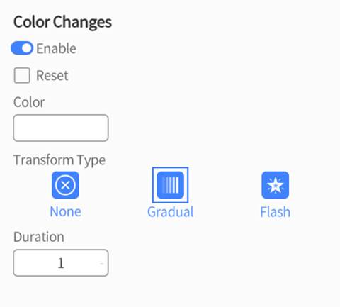
Transform Type
-
- None: The color of the element will directly change to the specified color without any animation effect.
- Gradual: The element’s color will transition into a new color over a period of time, creating a smooth and gradual change in color.
- Flash: The element will rapidly alternate between its original color and the new color within a certain time frame, creating a blinking or flashing effect.
After adding the Change Color action, during the scenario playback, when the element performs the action, its color will change according to the settings.