How Can We Help?
User interface
Homepage
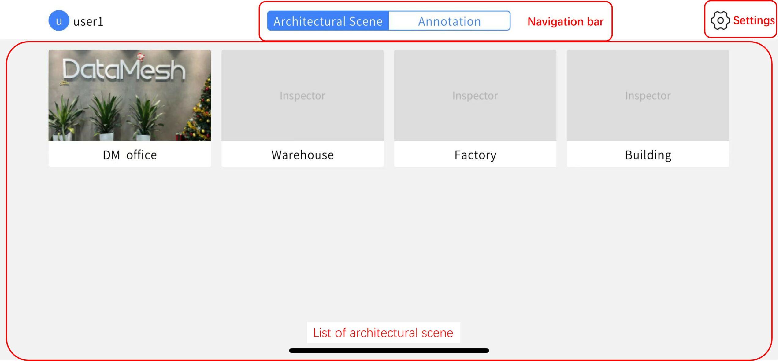
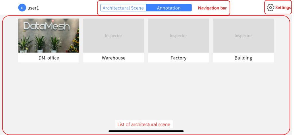
Homepage of architectural scene
Annotation
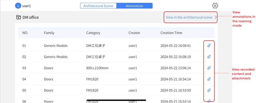
Press one of the architectural scenes to enter the annotation page.
Settings
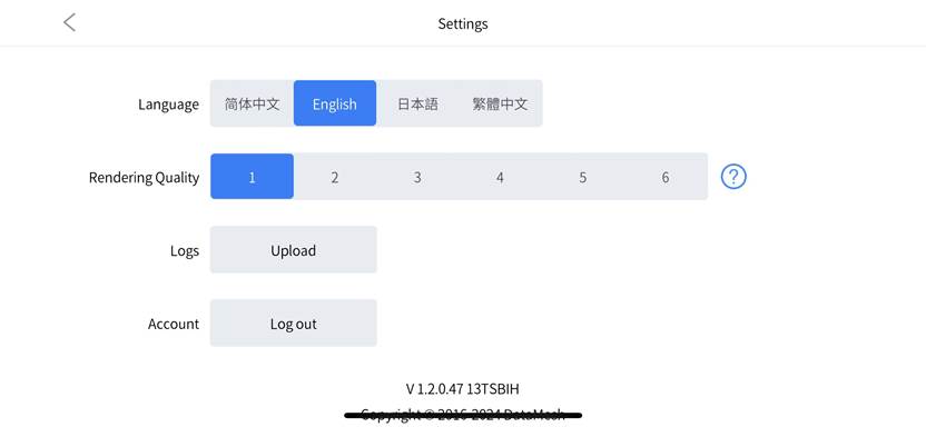
Language: You can switch the interface language to Simplified Chinese, English, Japanese, and Traditional Chinese.
Rendering quality: You can choose different rendering quality levels to adjust the clarity and level of detail in model rendering.
-
- 1 (Lowest Quality): The most basic rendering level, ideal for quickly viewing the model or when the device performance is limited.
- 6 (Highest Quality): The best image quality and detail display, but it may significantly impact software performance.
Logs: DataMesh supports uploading the latest seven logs.
Account: Click the Logout button to log out of the account and return to the login page.
Architectural scene interface
Roaming mode
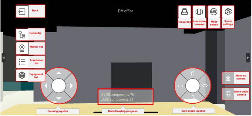
Left menu bar
The left menu bar includes the following options:
-
- Back: Return to the homepage.
- Geometry: Displays the hierarchical structure of the model.
- Marker list: Shows the markers for various positions in the scene, making it easier for you to navigate and locate quickly.
- Annotation list: Lists all annotations in the scene, allowing you to view and manage them.
- Equipment list: Displays the list of equipment included in the scene, enabling you to view and manage equipment information.
Control tools for viewing the architectural scene
The scene viewing control tool consists of two joysticks at the bottom and up/down arrows on the right:
-
- Panning joystick: The joystick located in the lower left corner is used for moving in all directions within the architectural scene. By sliding the joystick, you can move the camera in the corresponding direction.
- View angle joystick: The joystick in the lower right corner is similar to the Panning joystick, but its function is to rotate the camera and change the viewing angle.
- Up and down arrows: The interface also provides up and down arrows for adjusting the vertical position of the camera. You can use these buttons to raise or lower the camera’s position, changing the height of the viewpoint.
With these scene roaming control tools, you can roam freely within the architectural scene and adjust the viewpoint and camera height as needed for a better observation and experience.
Upper right menu
The menu in the upper corner includes:
-
- Resources: Used to view and add auxiliary resources.
- Annotation browser: Supports switching to the annotation browsing mode.
- Mode switch: Allows switching between 3D roaming mode and MR mode.
- Scene settings: In 3D roaming mode, scene settings include settings for dynamic loading range. This setting dynamically loads models within the corresponding range based on the position and perspective of the scene being viewed, ensuring smooth scene browsing and performance optimization.
Model loading progress
-
- Model loading progress displays the current number of components being loaded for the model, helping users understand the loading progress.
MR Mode
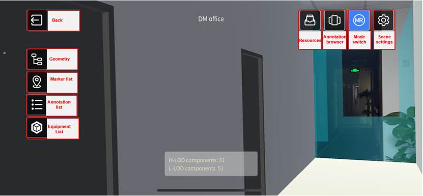
Left menu bar: Functions are the same as in the roaming mode interface.
Upper right menu: Functions are consistent with those in the roaming mode interface.
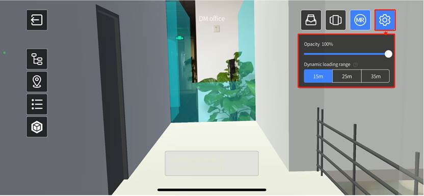
In the “Scene Settings” of MR mode, you can not only adjust the dynamic loading range according to your needs but also modify the opacity of objects in the scene to enhance your user experience and improve interaction effects.
-
- Opacity: You can adjust the opacity of objects in the scene, making them appear semi-transparent or fully transparent in the MR environment. This allows you to see the surrounding environment and other objects more clearly while browsing the scene, and also helps improve the visibility and usability of objects within the scene.
- Dynamic loading range: In MR mode, the loading range settings are used to determine the range of models displayed within the actual spatial location. This meets the needs for viewing 3D models, real space, and the integration effects of both in frontline business applications. This setting limits the total size of models in the space and continuously updates the models within the range as you move in real-time, ensuring smooth operation of the Inspector and providing you with a stable interactive experience.
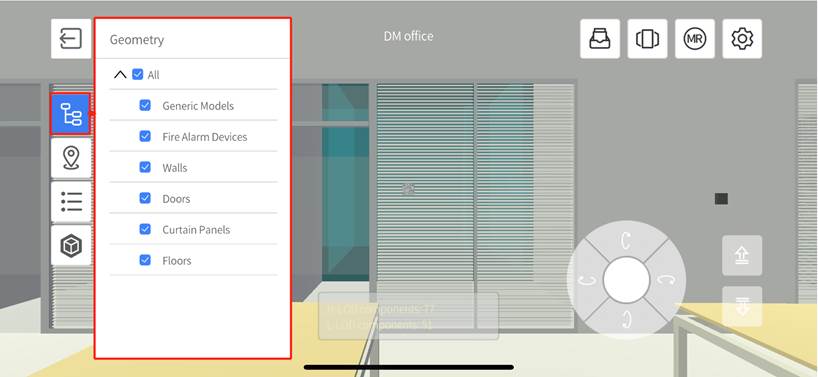
Geometry
The geometry automatically categorizes all components within the loading range based on their Category. Selecting a category makes the corresponding component models visible, while deselecting hides them. For instance, some walls situated in construction paths might be built in the later stages. During inspection, it is important to hide these yet-to-be-constructed walls for a clearer view. Therefore, selectively hiding certain components becomes essential.
Marker list
In the architectural scene, you can add markers to quickly pinpoint target locations in different modes.
-
- 3D roaming mode: By selecting a marker, you can quickly “land” at the target location.
- MR mode: After clicking the marker, you can rescan and relocate it.
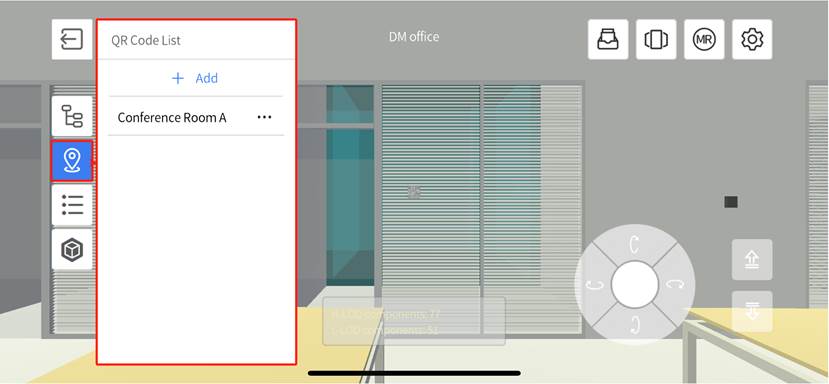
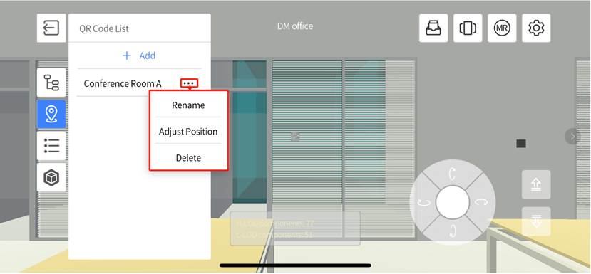
In the marker list, you can perform the following operations:
-
- Rename: Rename the marker for better management and identification.
- Adjust Position: Change the position of the marker in the scene to more accurately reflect the target location.
- Delete: Remove markers that are no longer needed.
- Add: Introduce new markers in the scene to accommodate new needs.
Annotation list
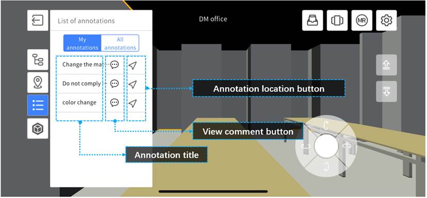
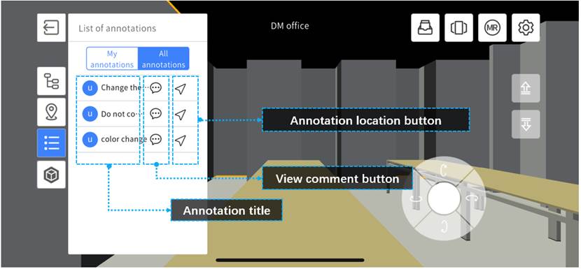
The annotation list documents the records, marks, and annotation content for each component. The list is categorized into two panels: My Annotations and All Annotations.
-
- My annotations: Display the annotation information created by you, one by one.
-
-
- Annotation positioning button: Clicking the annotation location button will take you to the corresponding component’s location. In roaming mode, clicking any annotation’s location button will switch the view to the recorded component’s location. In MR mode, clicking the annotation’s location button will display a navigation arrow on the screen, guiding you to the location of the recorded component..
- View comment button:
 denotes that the annotation has a comment, and a red dot in the upper right corner acts as a notification for new comments.
-
-
- All Annotations: Shows annotation names and the creator’s icon (displaying the user’s initials or the first character of their Chinese name).
-
- Annotation positioning button: Clicking the annotation location button will take you to the corresponding component’s location. In roaming mode, clicking any annotation’s location button will switch the view to the recorded component’s location. In MR mode, clicking the annotation’s location button will display a navigation arrow on the screen, guiding you to the location of the recorded component.
- View comment button:
 denotes that the annotation has a comment. There are no red dot notifications for new comments.
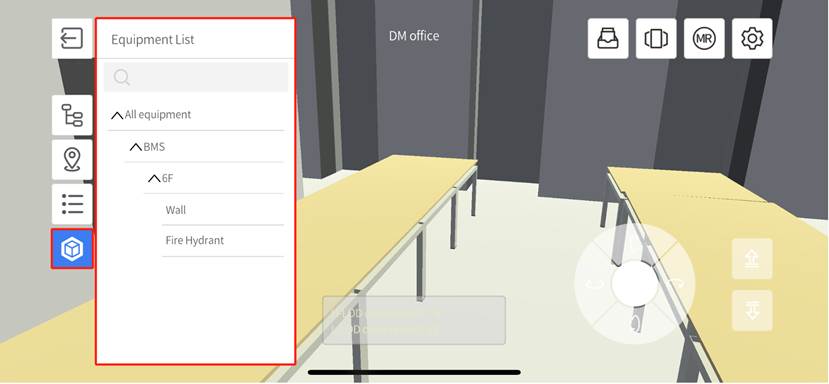
Equipment list
This feature allows you to view and quickly navigate to all equipment in the scene. By clicking on a piece of equipment, you can quickly navigate to the location of that equipment.
Component information panel
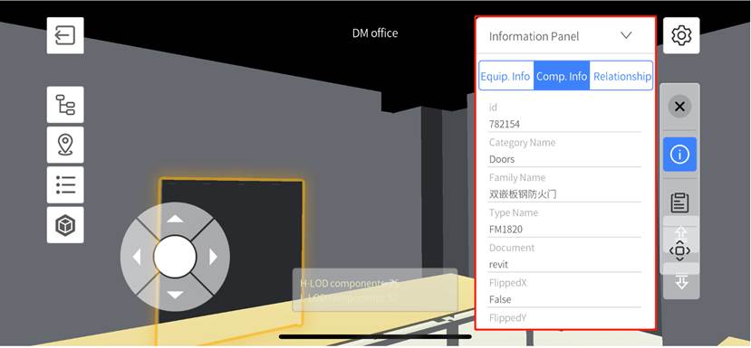
In the architectural scene, when you select a component, the edges of that component will be highlighted, and an information panel will pop up. The information panel displays important information such as the component’s BIM data and the business relationships of the equipment, helping you to understand and manage the components within the scene.
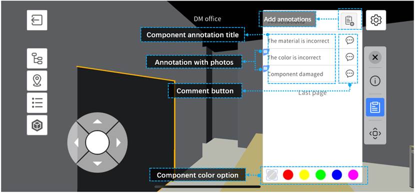
Component annotation panel
In the architectural scene, when you select a component, click the annotation button in the toolbar on the right. This action will open the annotation panel for the component, allowing you to view, add, edit, and delete annotations, as well as make comments for the annotations.
