How Can We Help?
Function introduction
Build a BIM scene
The process of building a BIM scene is shown in the diagram below:

- Convert BIM Models: Users can either use local tools to convert Revit files or contact DataMesh for model conversion services. The conversion will generate a .zip file containing the model and component information.
- Create BIM Scene: Create a new BIM Scene on the FactVerse platform, providing basic information such as name, directory, and description.
- Import Scene Resources: Upload and import the converted .zip file into the BIM Scene. The system supports importing multiple models by discipline (e.g., structural, architectural, electrical), making later integration more convenient.
- Build the Scene: Combine the imported discipline-specific models to construct a complete BIM Scene. This supports subsequent facility management and engineering inspection tasks.
BIM model conversion
You can use local tools to convert Revit files into the required format, or send an email to bimfile@datamesh.com to request the BIM model conversion service provided by DataMesh. Please review and confirm the relevant Service Level Agreement (SLA) before submitting your request.
The steps for local conversion are as follows:
1. Download the Plugin: Download the Inspector plugin.
2. Extract the Plugin: Unzip the downloaded file into a local folder.
3. Install the Revit plugin: Double-click the Revit plugin installer to begin the installation.
Note: Ensure that AutoDesk Revit is installed and not running during this process.
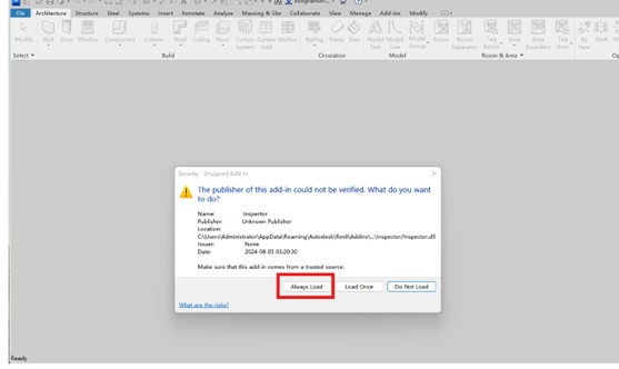
4. Open Revit: After installing the plugin, open Autodesk Revit for the first time. In the prompt dialog, click the Always Load button.
5. Convert the file
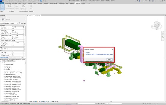
a) Open the file you wish to convert.
b) In the toolbar, navigate to Add-Ins – Inspector > Local.

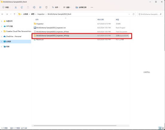
c) The file will be automatically saved as a Revit file once the conversion is complete.
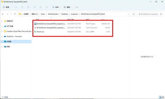
6. Locate the generated file
7. Install the 3ds Max plugin
Note: If installation fails due to antivirus software, please refer to the “Antivirus protection settings” section for assistance.
a) Download the 3ds Max plugin installation file.
b) Double-click the installation file to install the plugin. Note: Do not change the installation path of the plugin (startup path).
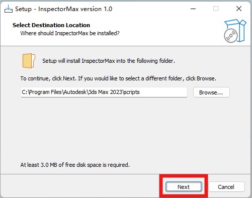
c) Confirm the installation path.
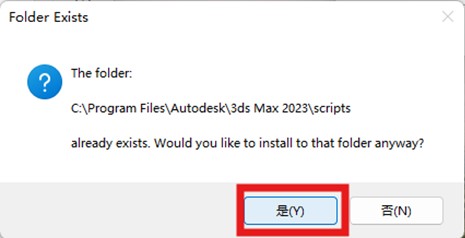
d) Click Install.
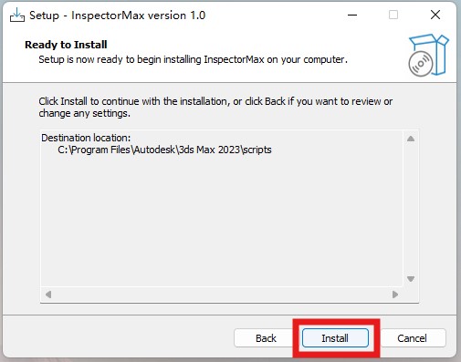
e) Click Finish to complete the installation.
8. Run the plugin
a) Open 3ds Max. If it is currently running, close it and reopen. You should now see the Inspector Local menu in the main menu bar.
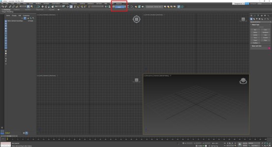
b) Click the Inspector plugin menu and select the target file, specifying the export directory in the pop-up window.
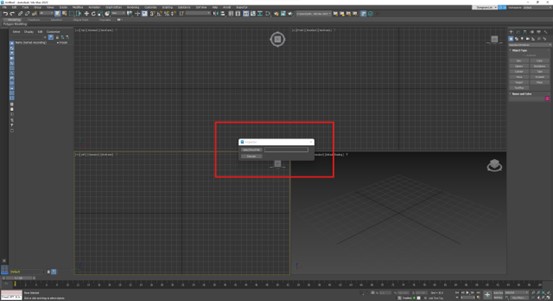
c) Click Execute.

d) If any components are missing, click to install them.
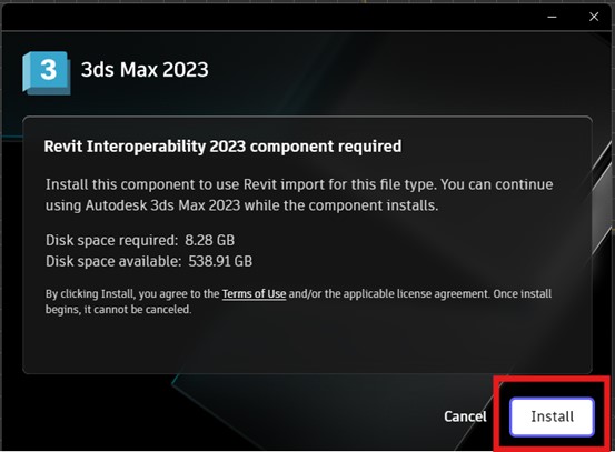
e) A zip file will be generated.
Create a BIM scene
The specific steps for creating a BIM scene are as follows:
1. Access the BIM Data page
On the DataMesh FactVerse platform, navigate to Digital Assets> BIM Data in the function module navigation bar to access the BIM Data page.

2. New BIM scene
a) In the BIM Data page, click New to open the New window.
b) Fill in the BIM scene information in the New window and click the Confirm button when completed.
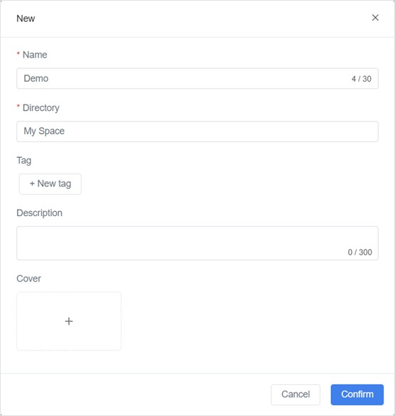
In the New window, you need to provide the following information about the BIM scene:
- Name (Required): The name of the BIM scene.
- Directory (Required): The storage directory for the BIM scene. After creating the scene, the system will create a hidden folder named after the BIM scene in this directory to store the constructed files and digital twins of the equipment. For example, after successfully creating the BIM scene “DM Office,” a hidden folder named “DM Office” will be automatically created in its directory.
- Description: You can add a brief text description to introduce or describe the BIM scene.
- Cover: You can choose a standard format image from your local files as the scene’s cover. Selecting an appropriate cover image can enhance the recognizability of the BIM scene.
Import scene resources
1. Upload Resource Files
Upload the .zip files generated from the BIM model conversion to Resources
2. Import Scene Resources:
a) On the BIM Scene Details page, click the [Import] button to open the [Select Resource] window.
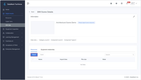
b) In the [Select Resource] window, select the required resource (the .zip file generated from the BIM model conversion) and click the [Confirm] button to import it into the BIM Scene.
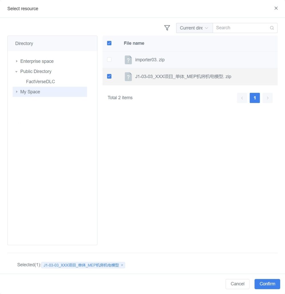
When a BIM scene is modeled separately by different disciplines, such as architecture, structure, electrical, plumbing, HVAC, etc., you can import the BIM models of each discipline into the same BIM scene. This way, in subsequent building steps, you can merge these models to create a complete large-scale BIM scene, supporting comprehensive facility management and engineering inspections.
c) After the file is imported, the system will show the file status as “Import successful, waiting for building.” At this point, you can proceed with the next steps in the scene building process.
Build the scene
1. Select files for construction: On the BIM Scene Details page, select all the files you want to build, then click the Build button.

2. Confirm processing consumption: A prompt will appear asking you to confirm the processing consumption. Note: In this version, there’s no need to worry about the consumption count—you can confirm the processing directly.
3. Check construction status: Files that are being built will be unselectable and show a “Building” status. You can manually refresh the page based on the “Estimated Completion Time” to see the latest status.

4. Construction Complete: Once the file status shows “Build Successful,” the scene has been successfully built. At this point, you can proceed with additional steps, such as importing other building models for incremental construction.

If a file fails to build, please contact support@datamesh.com for technical assistance.
Roam in the BIM scene
In Roaming Mode, you can closely inspect and review various parts of the building model within a virtual environment, facilitating the identification and adjustment of issues during the design and construction phases.
Follow these steps:
1. Log in to DataMesh Inspector.
2. Access the BIM Scene homepage, click on the BIM scene you want to view:
- When opening the BIM scene for the first time or if no marker has been added, it will default to Roaming Mode.
- For scenes with added markers, you can select the desired marker in the marker selection window and click the Roaming Mode button to enter Roaming Mode.

3. Browsing in the Roaming mode:

- Panning: Use the Panning Joystick on the left to pan and zoom in or out the camera view, effectively moving the camera position on a horizontal plane. By sliding the joystick, you can move the camera left, right, forward, or backward to explore different areas of the BIM scene.
- Rotation: Use the View Angle Joystick on the right to rotate the camera and change the viewing angle. This allows you to view the building model from various angles for a better understanding of its structure and design.

- Adjusting view height: The up and down arrow buttons are typically used to adjust the height of the view. This enables you to move up and down within the BIM scene to observe different levels or heights of the building.
Add markers
Markers are key position marks within the BIM scene, allowing you to quickly navigate to specific locations.
By adding markers for inspection areas in Roaming Mode, you can swiftly switch the camera position to those points, or place the corresponding building scene model in the corresponding position in real space, enabling you to view the BIM scene in MR mode.
Follow these steps:
1. After opening the BIM scene, when roaming to common locations such as entrances, passages, or rooms, click the Marker list button ![]() in the left-side functional navigation to expand the list.
in the left-side functional navigation to expand the list.

2. Click on the + Add button at the top, and a QR code icon will promptly appear at the center of the screen.

3. The QR code will follow the camera’s position and angle, and automatically attach to the nearest model in the center of your view. Use the joystick and the up/down arrows on the right to adjust the QR code to a location that is easy to recognize, then click the Drop button.

4. After placing the QR code, a rename window will pop up. Enter a name for the marker to easily distinguish the different locations it represents.

5. In the Marker list, you can rename, adjust the position, or delete any placed marker.

6. After adding markers, simply click on any marker in the list to swiftly “land” at the target location.
Manage 2D/3D resources
You can bind 2D assets and 3D models to components within the building model. 2D assets, such as drawings and images, can be attached to scene components to guide construction, illustrate process steps, and provide equipment operation documentation for maintenance. In contrast, 3D models can simulate equipment placement, aiding in the optimization of spatial layout and planning.
Add 2D/3D resources
The specific steps are as follows:
1. Open the Resource Directory:
a) In the BIM scene interface, click the resource button ![]() , then click Select resources.
, then click Select resources.

b) Click Select from the directory to open the Resource directory window.

2. Locate resource files: Navigate through folders or use the search function to find the desired resource files.
3. Add resources to the scene: Click on the resource file you wish to add, then select Add to the architectural scene.

An information panel for the resource will appear in the center of the scene, prompting you to “Click any component to attach.”

4. Attach resources:
a) Adjust the viewpoint to the component where you want to add the resource: In Roaming Mode, use the joystick to change the viewpoint and position; in MR Mode, move your handheld device to load component models into your view. The information panel for the resource will follow the scene’s movement, remaining centered on the screen.
b) Click on the component in the scene where you want to attach the resource, then click the Drop button on the resource information panel to complete the addition of the auxiliary resource. Note: You must complete the addition of the current resource before proceeding to the next one.

Once added, an anchor point will be visible on the selected component.

Edit 2D/3D resources
Edit 3D models
1. Open the resource editing menu: Click on the 3D model added to the scene to open the resource editing menu.

2. Change attachment:
a) Click the Change Attachment button。
b) Move the view to the component where the resource is to be added, then click on the component in the scene.
c) Click the Drop button on the resource information panel to reattach the resource to another component.
3. Pose adjustment: After clicking the Pose Adjustment button, conical arrows (movement joystick) corresponding to the X, Y, and Z axes will appear near the center of the model (X axis is red; Y axis is green; Z axis is blue).

- Move: Tap and drag the model with your finger to move it. Alternatively, click and drag the cone-shaped control handle to precisely move the model along a specific axis.
- Rotate: Clicking a conical movement joystick activates a circular rotation joystick perpendicular to that axis. For example, clicking the Y-axis conical arrow activates the circular rotation joystick in the XZ plane. Dragging the mouse anywhere on the rotation joystick in the XZ plane allows the object to rotate around the Y-axis.

- Zoom: Hold the rotation joystick (circular) at any position until the three conical movement joysticks disappear, then drag in the direction of the tangent perpendicular to the rotation handle to zoom the model or sub-object.
4. Delete: Click the Delete button to remove unnecessary resources from the current scene and simplify the scene content.
Edit 2D resources
1. Open the resource editing menu: Similar to 3D models, clicking on a 2D resource in the scene will open the resource editing menu.

2. Change attachment:
a) Click the Change Attachment button.
b) Move the view to the component where the resource is to be added, then click on the component in the scene.
c) Click the Drop button on the resource information panel to reattach the resource to another component.
3. View: By clicking the View button, you can toggle the display modes of the 2D resource, including full screen, collapse, drag, and zoom, to fit different scene requirements.

4. Delete: Like with 3D models, clicking the Delete button allows you to easily remove unnecessary 2D resources.
View BIM scene in MR mode
MR (Mixed Reality) Mode is a viewing method that combines virtual building models with real-world scenes. With MR mode, you can view virtual building models in a real environment, achieving a seamless integration of the virtual and the real, making it easier for on-site inspection and management.
Prerequisites
The BIM scene must already contain markers.
Specific steps:
1. Download and print Inspector Marker.
2. Select target marker and MR viewing mode: If you have returned to the homepage, when you click on the BIM scene again, you will need to select which mode to enter and where to position yourself in the scene. For example, to reach the office entrance in MR mode, you need to select the corresponding marker before entering MR mode.

3. Scan the marker: Place the prepared marker at the corresponding location on-site. Align the scanning box with the marker to complete the recognition.
4. View the BIM scene in MR mode: Move around with your handheld device, and component models will continuously load into your field of view, calculating and loading the BIM scene based on your real-time location.

5. Focus on the target component: In MR mode, while moving, select a target component. By clicking ![]() , an arrow pointing to the target component will appear on the screen, allowing you to move the camera according to the arrow’s guidance to easily find the target component. In roaming mode, click
, an arrow pointing to the target component will appear on the screen, allowing you to move the camera according to the arrow’s guidance to easily find the target component. In roaming mode, click ![]() to quickly return to the selected target component
to quickly return to the selected target component

6. View component information: Click on any component model to expand its data panel, displaying engineering information of the component.

7. Add component annotations:
a) Click the component annotation button ![]() to bring up the annotation panel.
to bring up the annotation panel.

b) Through the annotation panel, you can click ![]() to add text and image records for the selected component, as well as change the component’s color to describe any issues present.
to add text and image records for the selected component, as well as change the component’s color to describe any issues present.
Collaboration annotations
The collaborative annotations feature supports viewing and commenting on annotations made by other team members during the inspection process. Simultaneously, the annotation browser greatly enhances the visualization of annotations.
Create annotations
1. Open the component annotation panel: In the BIM scene, select the component and click the component annotation button ![]() to open the component annotation panel.
to open the component annotation panel.
2. Add a new annotation:
a) In the component annotation panel, click the add annotation button ![]() to open the annotation window.
to open the annotation window.

b) In the Annotation window, enter the annotation content and add a screenshot.

c) Click Done to complete the annotation addition.
Delete annotations
1. Select the annotation to be deleted: In the component annotation panel, click on the annotation to be deleted to open the annotation window.

2. Delete the annotation:
a) In the Annotation window, click the Delete button.

b) Click the Confirm button to confirm the deletion of the annotation.
Add annotation comments
The annotation comment feature supports viewing comments from other personnel and leaving comments during the inspection process.
1. Open the component annotation panel: Select the component and click the component annotation button ![]() to open the component annotation panel.
to open the component annotation panel.
2. Leave a comment:
a) In the component annotation panel, click on the comment button ![]() for the target annotation.
for the target annotation.

b) Enter the content in the comment box and click Send to comment on the annotation.

3. View comment: After adding a comment, the new message information will be displayed below the annotation.

Enable annotation browser
1. Enable the annotation browser: Click the annotation browser button ![]() to view annotations in the BIM scene.
to view annotations in the BIM scene.
2. View annotation information: In annotation browsing mode, component annotation information is displayed in bubble form, showing all annotation information within the user’s field of view.
3. Move annotation: Long-press on the annotation information, when it turns blue, you can drag and relocate it to another position.

View annotations
When you need to revisit historical inspections, you can find the target annotation in the annotation list on the Annotation homepage. Click to view the content of each annotation record. During the review, you can modify or add record content using the same methods as in regular inspections.
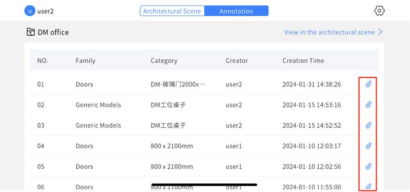
The specific steps to view annotations are as follows:
1. Select the target BIM scene: Click the target BIM scene in the BIM scene list on the Annotation homepage.
2. Enter roaming mode: Click View in the architectural scene to enter roaming mode.
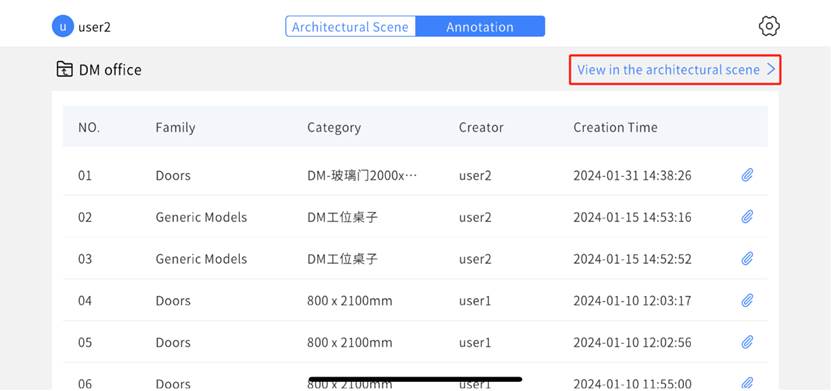
3. Place the marker: Place the printed marker in the inspection area on site.
4. Switch to MR mode: Click the MR mode toggle button and scan the marker placed on site to enter MR mode.
5. Conduct the inspection:
a) In the BIM scene, click the resource information panel to open and view the auxiliary materials added to the scene.
b) Adjust the scene model’s transparency for better comparison during the inspection.
c) Create, delete, modify annotations, or add comments. For more information, please refer to Collaboration annotations.
d) Click the color option to mark the selected component with color.
6. Complete the inspection: Once the inspection is finished, click the return button in the upper left corner to exit.
Annotation task management
On the Annotation Task Management page of the FactVerse platform, you can view and manage various annotation contents, and you can export the annotation list in Excel format.
1. Create a new annotation task: In the FactVerse platform, go to Work of Acceptance > Annotation Task Management page and click the New button.

2. Fill in task information: In the new task window, enter the annotation task name, associate it with the relevant BIM scene, and click the Confirm button after completing the information.

3. View annotation records: On the Annotation Task Management page, click the details button ![]() corresponding to the task you want to view to open the annotation record page.
corresponding to the task you want to view to open the annotation record page.

4. Export annotation records: On the annotation record page, click the Export Excel button to download the annotation record file to your local device.

5. View annotation records: Open the annotation record file to review the annotation records.

Create equipment digital twins in the BIM scene
Using DataMesh Inspector to support facility maintenance and building operations requires the creation of digital twins for equipment and the definition of business relationships between the equipment.
Create equipment digital twins
1. Create digital twin template: Use the FactVerse platform or FactVerse Designer to create a digital twin template for the target equipment based on actual business needs.
2. Export Template: Export the Excel template from the BIM scene, which includes sample data.
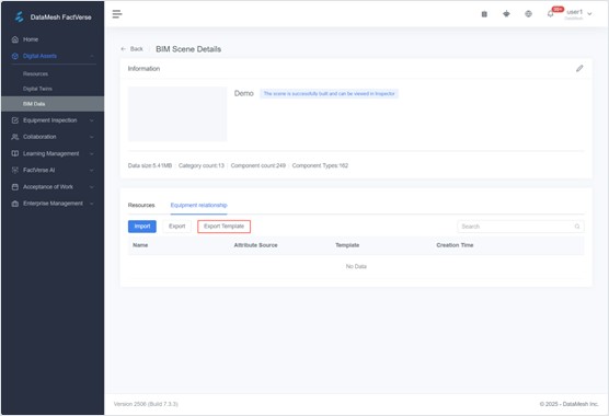
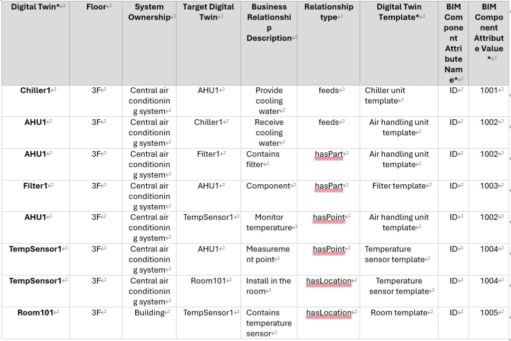
3. Fill in the Excel template: Refer to the equipment business relationships in your equipment management system (such as Building Management System) to fill in the following information in the template:
- Digital Twin information:
- Digital Twin (Required): The name of the digital twin to be created. The created digital twin will be automatically saved in the hidden folder of the BIM scene.
- Floor: The floor where the equipment is located.
- System Ownership: The system to which the equipment belongs.
- Equipment Business Relationships: After adding business relationships, you can view the relationships between equipment in the DataMesh Inspector in conjunction with the real environment.
- Target digital twin: The digital twin of the equipment that has a business relationship with this equipment.
- Business Relationship Description: A description of the business logic relationship for the created digital twin.
- Relationship Type: Relationship types defined based on Brick Schema, with 4 options provided by the system:
- feeds: Indicates that one device provides services, resources, or data to another device or system. For example, a chiller provides cooling water to an air handling unit.
- hasPart: Indicates that a device is part of another device or system. For example, an air handling unit may include components like fans and filters.
- hasPoint: Indicates the relationship between a device and its measurement or control points. For example, an HVAC system may have multiple temperature sensors to monitor temperatures in different areas.
- hasLocation: Indicates the relationship between a device and its location. For example, a temperature sensor is installed in a specific room to monitor the temperature of that room.
- Information Required for Creating Digital Twins:
- Digital Twin Template (Required): The name of the digital twin template used for the equipment, such as a generic cabinet template.
- Digital Twin Template External ID: If a template with the same name exists in the current tenant’s digital asset catalog, use the External ID to help the system accurately locate the template when creating the digital twin.
- BIM Component Information: Information about the BIM components that match the digital twin of the equipment.
- BIM Component Attribute Name (Required): An attribute from the BIM component, such as Element ID or Name, used to bind the digital twin created from this row of information.
- BIM Component Attribute Value (Required): The attribute value of the BIM component used to bind the digital twin created from this row of information.
Notes:
- The two rows highlighted in yellow in the template are example data. To avoid accidental edits, these cells are locked for protection; please start filling in from row 5.
- Ensure all required information is correctly filled out and check that the format of the template complies with system requirements before importing.
4. Import Excel template: On the BIM Scene Details page, click the Import button to upload your completed Excel file. Note: Before importing, make sure the templates required for the “Digital Twin Template” column are already created.
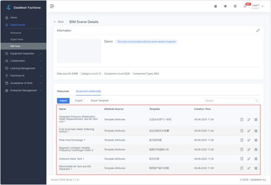
The system will generate digital twins for each piece of equipment based on the imported information and associate them with BIM components in the scene. The generated digital twins will appear in the digital twin list in the Equipment relationship panel, and the relationships can be displayed in both relationship diagram and table formats.
Excel spreadsheet sample
Below is an example of an Excel spreadsheet used to create digital twins for the central air conditioning system devices in Room 101 on the third floor.
View equipment business relationships
In the BIM Scene Details page on the FactVerse platform, check the generated digital twin list of equipment to ensure that all equipment digital twins and their business relationships are correct.
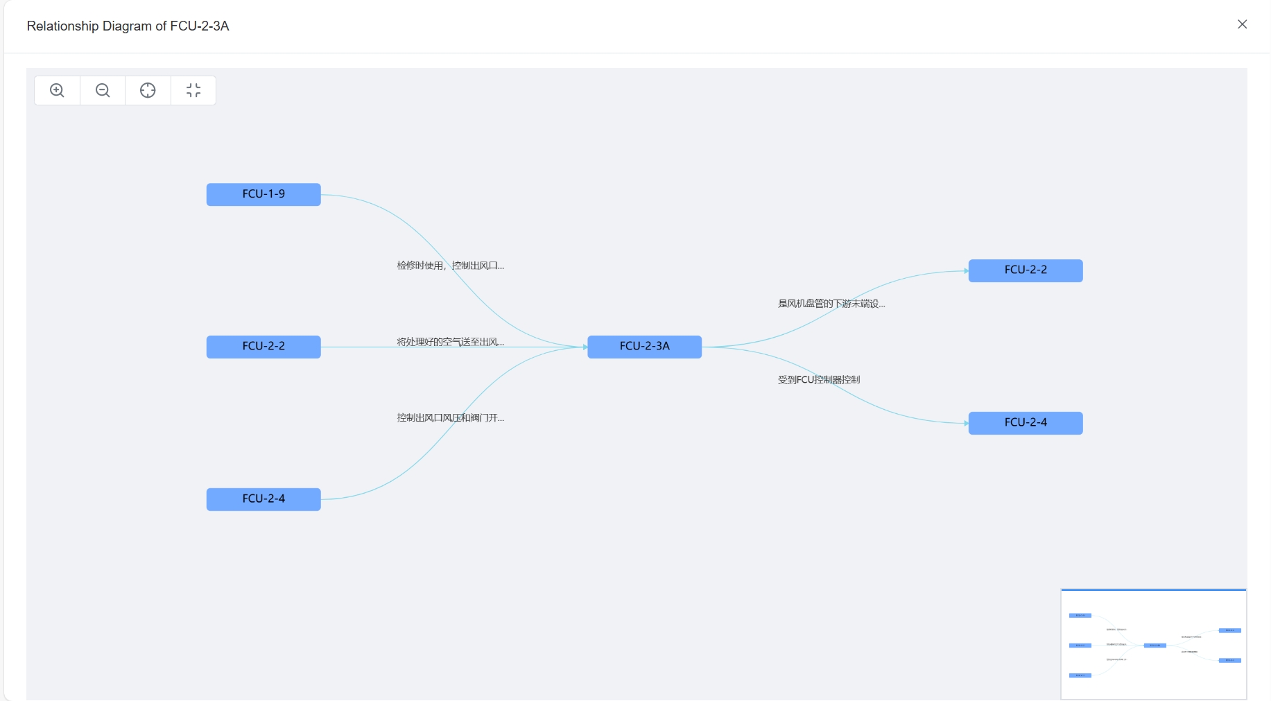
- Relationship Diagram: Click the “Relationship Diagram” icon
 , and the system will display the connections between the selected digital twin and other digital twins in a graphical format. Through the graphical interface, you can intuitively understand the upstream and downstream relationships, control relationships, etc., between the equipment.
- Relationship Table: Click the “Relationship Table” icon
 , and the system will list detailed information about all relevant digital twins in a tabular format, including relationship types, target digital twins, business relationship descriptions, etc.

Adjust equipment business relationship
Based on actual requirements, manually edit the business relationships of equipment digital twins in the equipment relationship list page within the BIM scene. This ensures alignment between real-world business needs and the digital twins.
- Add relationship:
-
- On the equipment relationship list page for the BIM scene, click the New button to open the creation window.
- Select the Target digital twins and Relationship type.
- (Optional) Enter a description of the business relationship.
- Click Confirm to save the new relationship.
- Modify relationship:
- Locate the relationship entry you want to modify in the relationship table.
- Click the edit button
 to open the Edit
 - Update the target digital twin, relationship type, or business relationship description.
- Click Confirm to save the changes.
- Delete relationship:
- Find the relationship entry you want to delete in the relationship table.
- Click the delete button
 , and the system will prompt you to confirm the deletion.
 - Upon confirmation, the relationship will be removed from the list, and the association will no longer be valid.
View equipment facilities in 3D or MR mode
In DataMesh Inspector, you can view equipment facilities in 3D or MR mode by following these steps:
1. Log in to DataMesh Inspector.
2. Open the BIM scene: Select either Roaming mode or MR mode to enter the BIM scene.
3. Roam and locate equipment facilities: As you navigate the scene, all created digital twins will glow, helping you quickly identify equipment. You can also click on devices in the equipment list to quickly locate the corresponding facility.

4. View equipment information:
- Click on an equipment digital twin to access detailed equipment information and business relationships. Connected equipment will be linked by yellow dashed lines, with description boxes for the business relationships.
- Use the Show/Hide All button to show or hide all associated business relationships for that equipment. You can also toggle the visibility of specific business relationships by clicking the corresponding on/off button.
