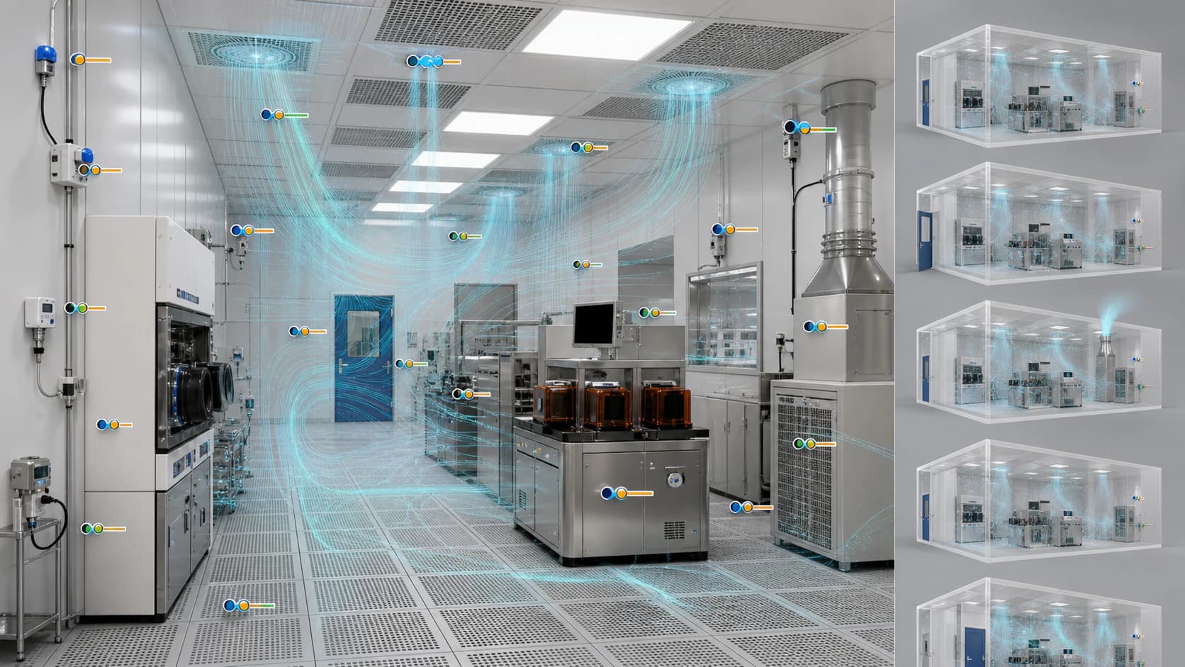
Cleanroom evidence should follow the decision
Airflow, species transport, local exhaust, and detector studies can support several levels of work: early option screening, measurement planning, facility-specific comparison, resilience review, and defined engineering decisions. Each level deserves a matching evidence package.
A cleanroom image can appear physically plausible while key source, ventilation, detector, or boundary assumptions remain uncertain. Technical buyers therefore need to see how the baseline was established, which measurements were used, how residuals were reviewed, what scenario range was evaluated, and which evidence remained independent from calibration.
This guide applies the broader DataMesh simulation-evidence framework to cleanroom and process-area studies. For the complete general framework, use:
- How to Evaluate Simulation Evidence for model purpose, inputs, verification, validation, uncertainty, and handover
- Calibration Levels and Confidence in Simulation Claims for exploratory, benchmarked, measured-data calibrated, and scenario-specific evidence
- Scenario Ensembles and Conservative Simulation Review for ranges, repeated runs, interactions, and decision cases
Select evidence around the cleanroom question
| Intended decision | Priority evidence | Typical review output |
|---|---|---|
| Compare airflow patterns or layout concepts | Reviewed geometry, ventilation states, boundary assumptions, solver checks, and sensitivity | Relative flow behavior, sensitive zones, missing data, and next measurement step |
| Evaluate local exhaust capture | Source and hood geometry, exhaust flow and pressure, room airflow, tracer or qualified field evidence, and residuals | Capture comparison, escaped material, affected zones, and uncertainty |
| Review detector placement | Source matrix, ventilation states, species transport, detector response assumptions, repeated runs, and selected validation evidence | Coverage comparison, detection-time distribution, potential blind spots, and conservative case |
| Assess heating, ventilation, and air-conditioning (HVAC) degradation | Verified baseline, equipment and door states, transient measurements, source profile, and scenario range | Affected-zone growth, timing, sensitivity, response priorities, and recovery behavior |
| Support a facility-specific engineering decision | Representative measurements, calibration record, independent validation, uncertainty, qualified review, and revalidation triggers | Decision conclusion within a defined evidence envelope |
The evidence scope should reflect the consequence of error, the cost of action, and the degree of facility specificity claimed by the result.
Establish a benchmark before site calibration
A benchmark checks whether the analysis workflow reproduces recognized or controlled behavior for selected variables. It helps separate method qualification from facility-specific parameter tuning.
Cleanroom-relevant benchmarks can include:
- a controlled airflow or pressure case with known geometry and boundary conditions
- a tracer or transport case with documented source and measurement locations
- a hood or exhaust case with an agreed reference result
- conservation and mass-balance checks over the selected domain and boundaries
- mesh, time-step, convergence, repeatability, and numerical-sensitivity checks
- comparison with another qualified method for a defined variable and condition
The benchmark record should state the variables compared, locations, units, acceptance criteria, result scale, method version, and known mismatch. Passing one benchmark supports the defined behavior that was tested.
Calibrate against representative facility evidence
Calibration adjusts selected uncertain parameters so agreed model outputs align more closely with representative observations. Parameter choice should preserve physical meaning and follow the intended decision.
Evidence that may support calibration
- supply, return, exhaust, fan filter unit, hood, and branch flow measurements
- pressure relationships across rooms, doors, floors, ceilings, and utility spaces
- airflow velocity and direction at decision-relevant locations
- temperature, humidity, or thermal-load evidence where buoyancy matters
- tracer concentration history, arrival time, decay, or qualified visualization evidence
- detector response records with calibration, setpoint, location, and equipment-state context
- door, damper, fan, process, tool, and source states during the measurement period
Parameters that may require review
- flow resistance, leakage, diffuser, grille, or floor characteristics
- exhaust, fan, damper, filter, or equipment performance
- source rate, profile, direction, momentum, temperature, or release duration
- turbulence, mixing, diffusion, wall, deposition, or species assumptions selected for the method
- detector response, threshold, sampling, delay, or averaging representation
The calibration record should preserve the baseline result, selected parameters, allowed ranges, objective function, measurement uncertainty, residuals, acceptance criteria, and reviewer approval.
Read residuals by location, time, and operating state
A residual is the difference between a measured value and the corresponding simulated value at an agreed location, time, or condition. Cleanroom studies often involve strong spatial and transient variation, so a single average can hide decision-relevant mismatch.
Review residuals across:
- supply, return, exhaust, hood, and room airflow measurements
- pressure boundaries and door states
- locations upstream, near, and downstream of major equipment or obstructions
- stable, transition, degraded, and recovery periods
- tracer or species arrival, peak, decay, and persistence
- detector locations and response times
- calibration and independent validation datasets
Useful summaries may include mean error, absolute error, bias, percentile error, time shift, spatial pattern, and the proportion of points within agreed limits. Acceptance criteria should follow measurement uncertainty, intended use, variable importance, and consequence of error.
Build a traceable scenario matrix
Calibration describes fit for selected evidence. The scenario matrix describes the operating and source range evaluated for the decision.
Each scenario should retain:
- source location, species, rate or profile, direction, duration, and temperature
- geometry, tool, enclosure, partition, and obstruction state
- supply, return, exhaust, fan filter unit, damper, pressure, and door state
- thermal and process conditions relevant to transport
- detector layout, technology, response, and threshold assumptions
- initial conditions, start time, duration, and represented response action
- model version, parameter set, checks, outputs, warnings, and review status
A matrix view lets buyers confirm coverage by source family, room, operating state, and consequence category. It also exposes combinations that require future study or field evidence.
Use repeated runs when timing varies
Detection time and transient transport can vary with initial conditions, source behavior, ventilation, model parameters, and numerical effects. A controlled repeated-run method turns that variation into reviewable evidence.
The project should define:
- which variables change between runs
- the distribution, range, or selection rule for each variable
- the number of runs and convergence or stability criterion
- the random seed or sampling method where relevant
- the detection threshold and response calculation
- how unresolved runs are represented
- the statistic selected for the decision
Useful outputs include the full detection-time distribution, median, selected upper percentile, earliest and latest credible result, proportion meeting a criterion, and scenario combinations associated with slow response.
A conservative statistic should have a stated rationale. The choice may reflect decision consequence, scenario coverage, evidence quality, and qualified engineering judgment.
Reserve evidence for validation
Validation compares model output with suitable evidence for the intended use. Strong projects reserve a measurement period, operating condition, source case, benchmark, or test from parameter tuning.
The validation record should identify:
- variables, locations, operating states, and source conditions compared
- measurement and test uncertainty
- residual or comparison metrics
- acceptance criteria and review rationale
- agreement and mismatch across spatial and transient behavior
- the conditions covered by the resulting claim
- responsible engineering approval
Evidence from a different source position, ventilation state, door event, load, or time period can reveal whether the calibrated behavior remains useful across the intended decision range.
State the evidence envelope beside the conclusion
The evidence envelope defines the variables, locations, source families, ventilation states, geometry, detector assumptions, operating range, and time horizon supported by the available proof.
Examples of proportionate conclusions include:
| Evidence level | Proportionate cleanroom conclusion |
|---|---|
| Exploratory | The scenario comparison identifies likely transport patterns and measurement priorities under documented assumptions |
| Benchmarked | The workflow reproduces the selected reference behavior within the reported checks and supports the defined comparison |
| Measured-data calibrated | The model supports facility-specific comparison for the calibrated variables, locations, and operating range within reported residuals |
| Scenario-specific validated | The evidence supports the stated engineering decision for the validated source, ventilation, detector, and operating conditions, subject to qualified approval |
Every conclusion should carry its evidence level, assumptions, uncertainty, reviewer, and revalidation triggers.
Define revalidation triggers at handover
Cleanroom facilities evolve. Revalidation should be reviewed after material changes to:
- room, tool, enclosure, partition, door, floor, ceiling, or obstruction geometry
- supply, return, fan filter unit, general exhaust, local exhaust, damper, or pressure control
- source species, location, rate, direction, duration, temperature, or process state
- detector technology, location, orientation, response, setpoint, or maintenance condition
- sensor identity, location, calibration, sampling, synchronization, or data quality
- operating range, decision consequence, acceptance criteria, or intended use
- observed facility behavior that moves beyond the agreed residual or evidence envelope
The response can range from a data review and targeted rerun to recalibration, a new benchmark, an independent test, or a full model update. Qualified owners select the response according to the significance of the change.
Technical buyer checklist
Purpose and ownership
- Is the intended decision, consequence of error, and required evidence level defined?
- Are facility, process, environmental health and safety, quality, compliance, and model-review responsibilities assigned?
Benchmark and calibration
- Which benchmark qualifies the selected method for the decision variables?
- Which measurements were used for calibration, and are they representative?
- Which physical parameters were adjusted, and what ranges were allowed?
- Are baseline results, residuals, measurement uncertainty, and acceptance criteria preserved?
Scenarios and ensembles
- Does the matrix cover credible source, ventilation, exhaust, door, tool, and detector states?
- Which variables change across repeated runs, and how are they sampled?
- Are distributions, unresolved cases, and conservative statistics reported transparently?
Validation and claims
- Which evidence remained independent from parameter tuning?
- How does performance vary by location, time, source, and operating state?
- Does the conclusion stay within the documented evidence envelope?
- Are model limits, uncertainty, and revalidation triggers visible?
Handover
- Can the model, data, scenario, result, finding, and approval record be traced?
- Can approved actions enter controlled inspection, maintenance, procedure, detector, or change workflows?
- Is post-change verification defined?
Evaluate one decision end to end
A focused evidence pilot can start with one cleanroom bay or process area and one engineering decision. The project establishes a verified baseline, selects a manageable source and operating matrix, reserves independent evidence, runs calibration and scenario comparisons, and records qualified review.
Strong pilot outcomes include:
- traceable facility, ventilation, source, detector, and measurement evidence
- a qualified benchmark and preserved pre-calibration baseline
- residuals and uncertainty linked to decision-relevant variables and locations
- a reproducible scenario matrix and repeated-run method where timing varies
- independent validation evidence and a clear evidence envelope
- one approved engineering, monitoring, inspection, exhaust, or detector decision
- handover records and revalidation triggers suitable for future facility change
Apply this framework to Cleanroom Airflow and Gas-Dispersion Evaluation, Local Exhaust Capture and Ventilation Degradation Scenarios, and Detector Coverage, Blind Spots, and Placement Options.
Public references
The National Institute of Standards and Technology review of industrial verification, validation, and uncertainty quantification describes model quality, analyst quality, verification, validation, and uncertainty as contributors to simulation credibility.
The American Society of Heating, Refrigerating and Air-Conditioning Engineers (ASHRAE) Clean Spaces handbook chapter describes cleanroom computational fluid dynamics, airflow, contaminant propagation, equipment effects, openings, supply, return, exhaust, and boundary conditions.
The International Organization for Standardization (ISO) 14644-4:2022 cleanroom lifecycle page covers requirements, design, construction, start-up, verification, modification, and lifecycle considerations.
The United Kingdom Health and Safety Executive guide on the selection and use of flammable gas detectors identifies gas properties, dispersion, ventilation, process equipment, sensor type, location, and redundancy as detector-system considerations.